A new youtube video has been published on our youtube channel.
The youtube channel ‘Learn for Life’ has posted multiple videos on a “free energy water pump’. Because we were sceptical whether this pump works or whether the video is fake we decided to build the pump ourselves.
You can watch the video below. Don’t forget to also have a look at the other videos at our channel
Since last year, the WOT has been in contact with HGI, an organisation that focuses on solving the plastic waste problem on small islands in the Moluccas. Several projects have been worked on since then.
Shredder
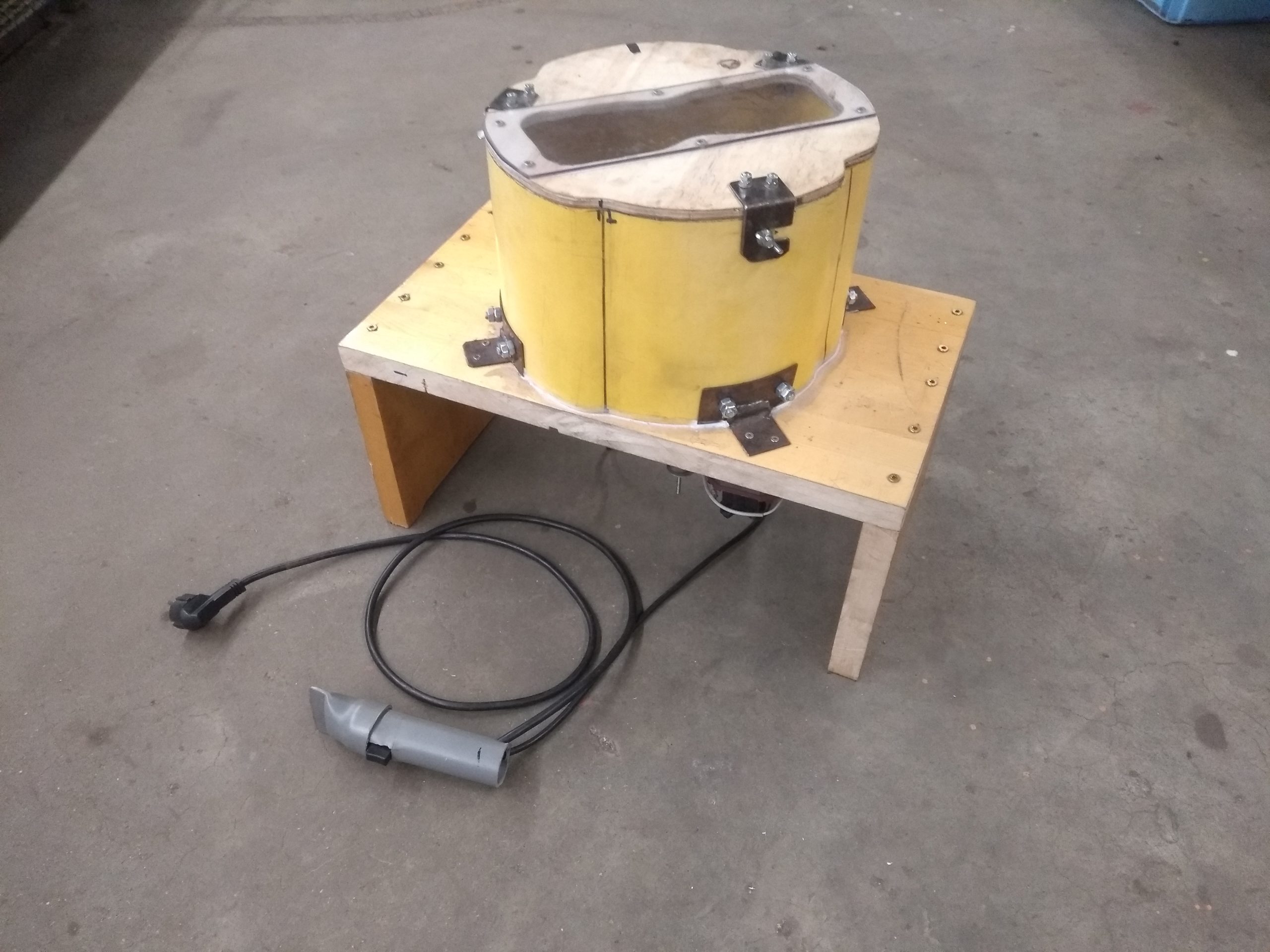
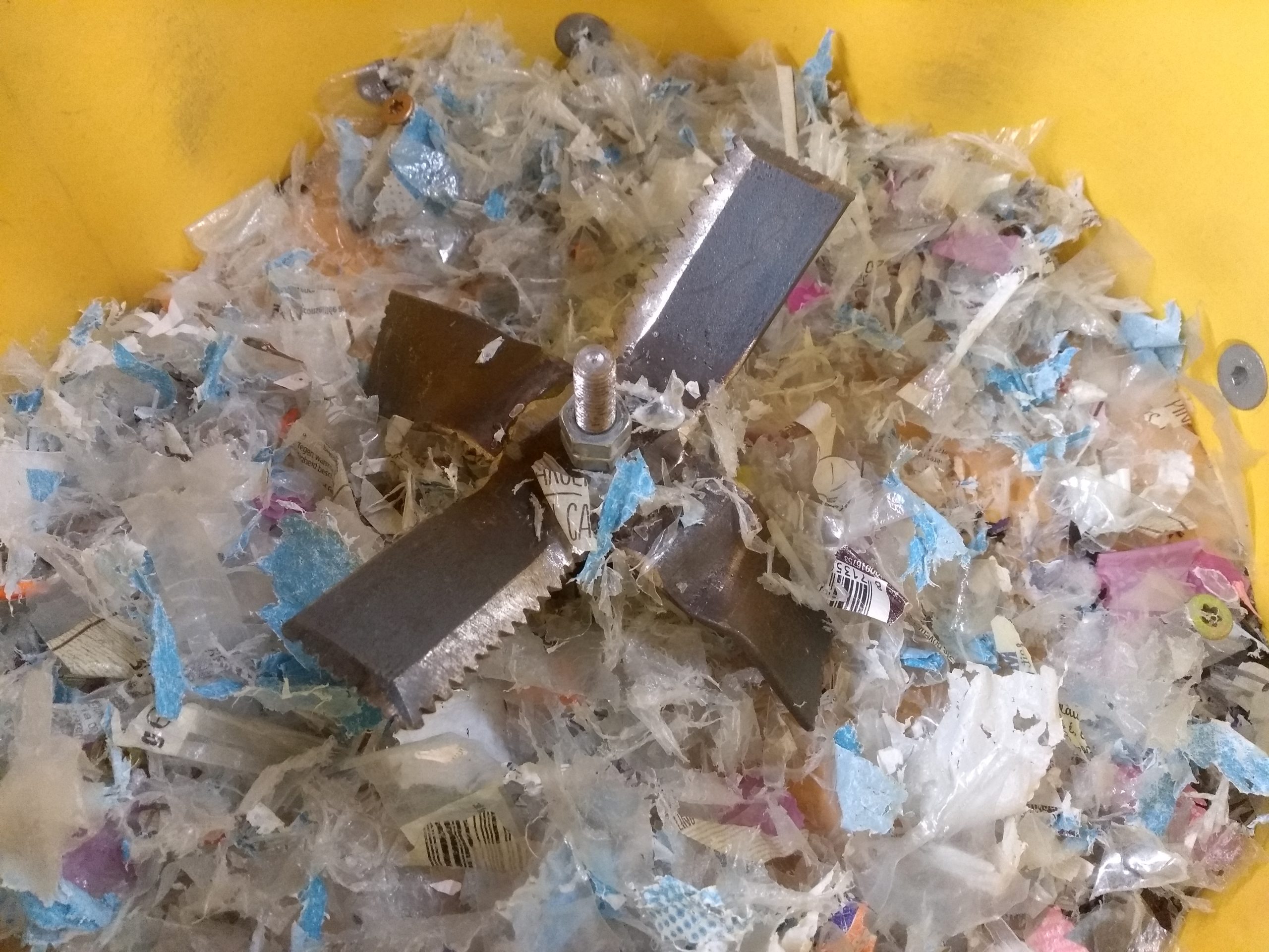
First of all a shredder has been made. Most commercially available shredders use rolls with teeth to slowly grind plastic into small pieces. The tolerances on these machines should however be rather small for it to function properly. Often advanced machines are used such as a laser/plasma cutter or parts have to be bought, to fabricate these types of shredders. The idea behind building the shredder at the WOT was to investigate if it would also be possible to create a shredder which requires less precise parts and can be made with widely available tools.
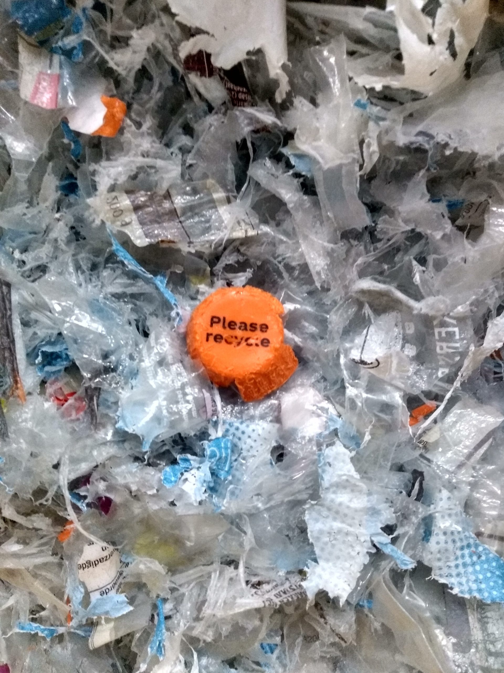
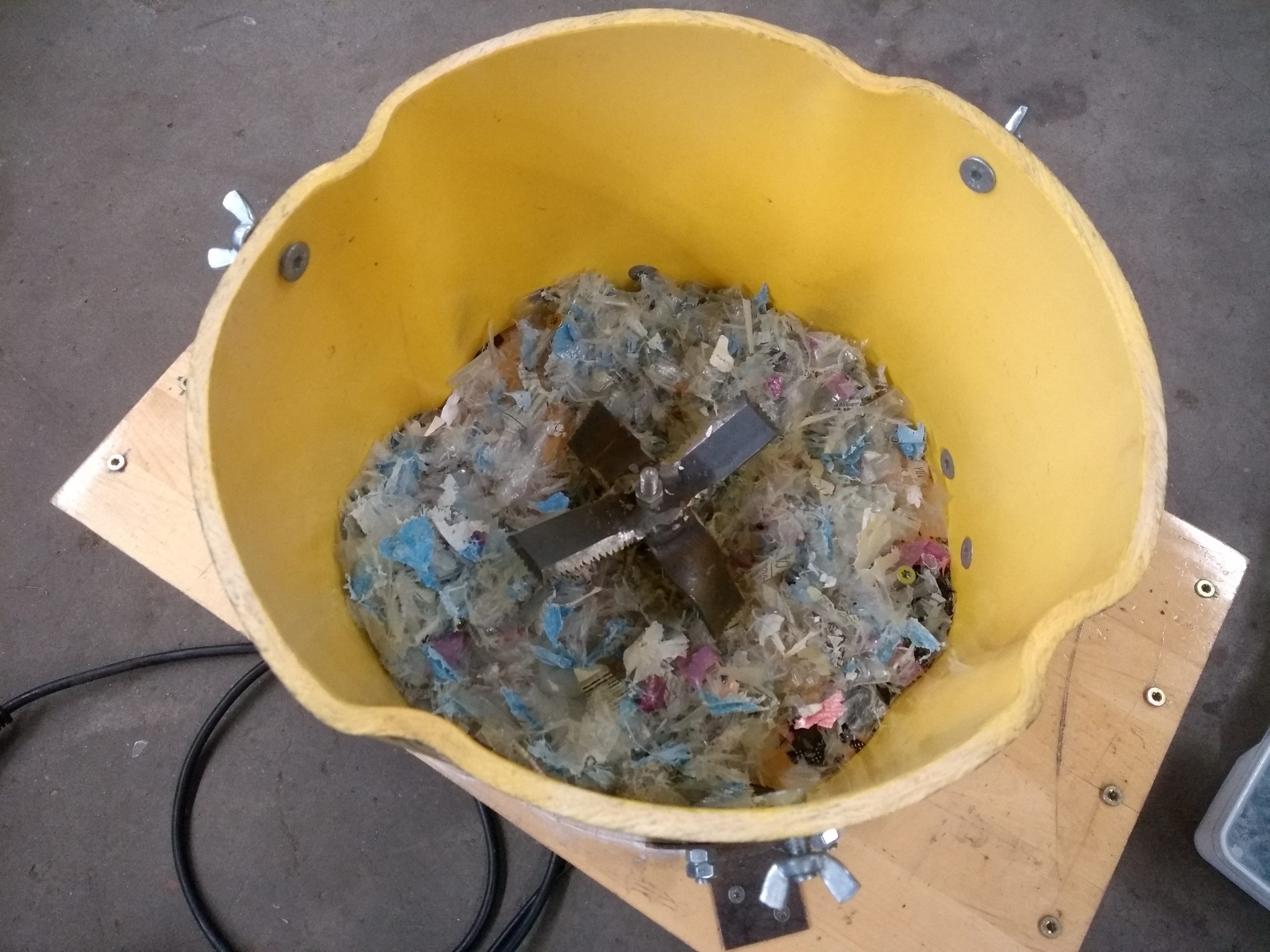
In this case an engine from an electric lawnmower has been used, mounted on a wooden frame and a custom blade was made. The shredder basically resembles a large blender. A mix of plastic waste (mostly packaging waste) was put in the shredder. This was a mix of PE and PP films (such as plastic bags) and harder products from PE,PP or PET.
After some tests, teeth were filed into the blade to decrease the possibility of film winding around the blade. After this adjustment the shredder performed reasonably well. It did not shred material quickly, but, with some help it was able to shred film, which is a difficult material to shred for most shredders. This shredder serves as a proof of concept to show it is possible to shred plastic without an advanced setup. Further research should be done to see if the shredding process can be made more efficient so it takes less time. Also, still some foil winded around the blades, further improvements might mitigate this. If these problems are solved a more generic model (with construction manual) may be designed.
Melting oven
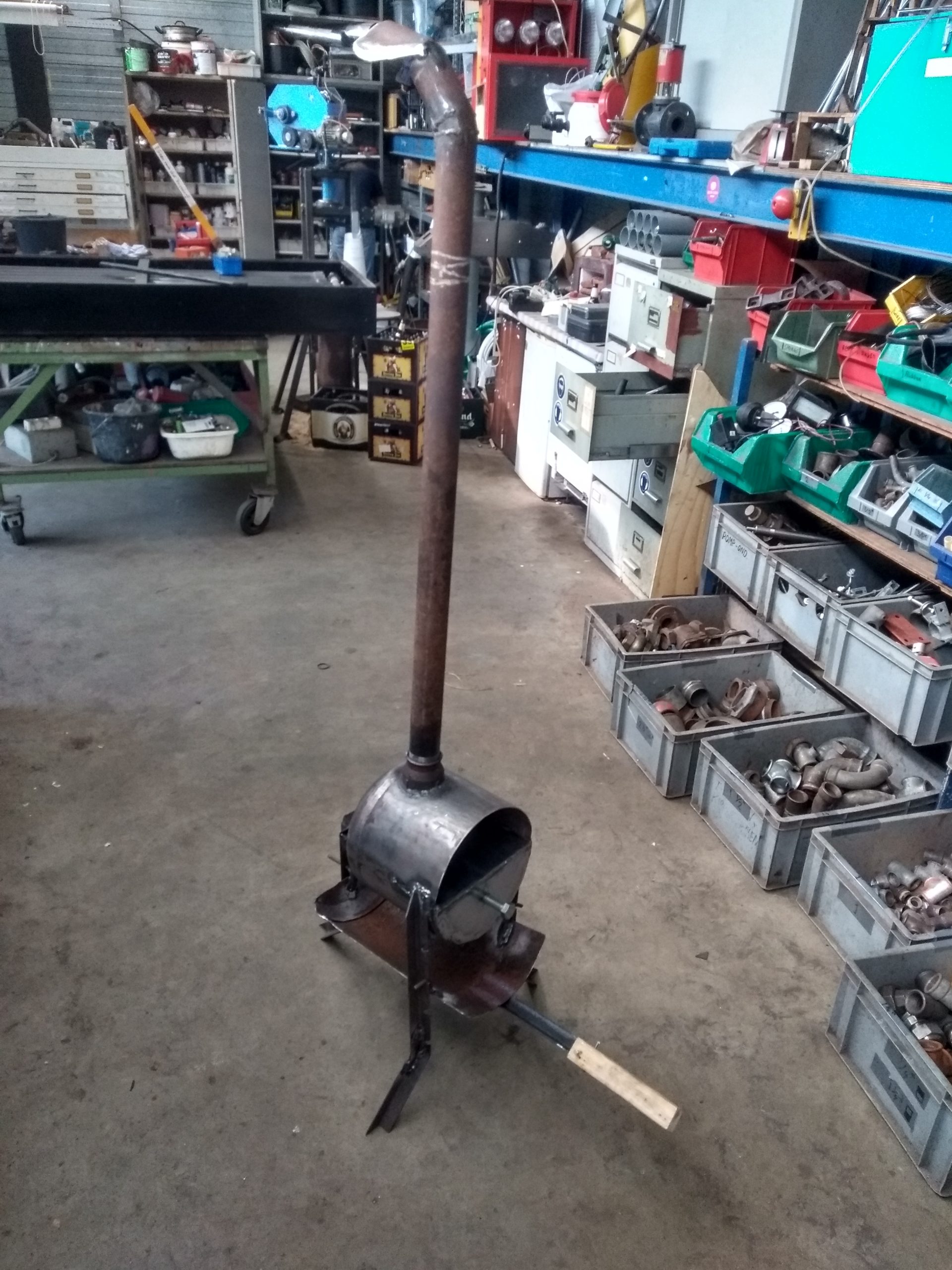
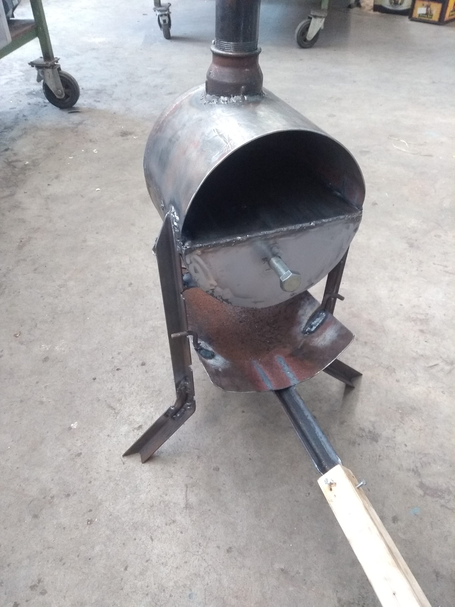
Furthermore a melting oven was designed that can be used to melt the plastic. The molten plastic can then be pressed in a mould to form a product. The oven was designed to work on woodfire. Often electric heating elements are used to melt plastic, but the choice for fire was made because the product was designed to be as accessible to as many people as possible, and the large electricity demands for heating may be a limiting factor for people.
Fire is made on the lowest plate, of which the height can be adjusted. The bottom half of the oven is filled with sand to act as a buffer. This way temperature regulation is more controlled. Plastic is placed and melted in the top half of the oven.
Tests using the oven revealed that it was suitable for melting plastic, but that the temperatures reached were not high enough for melting PET properly. Possibly the buffer region could be made thinner to allow the oven to heat up further, but a more feasible approach is to separate the PET from the PE and PP. Also mixing the plastic when molten in the oven was difficult, the plastic is very viscous and the oven does not allow for great access.
Extruder
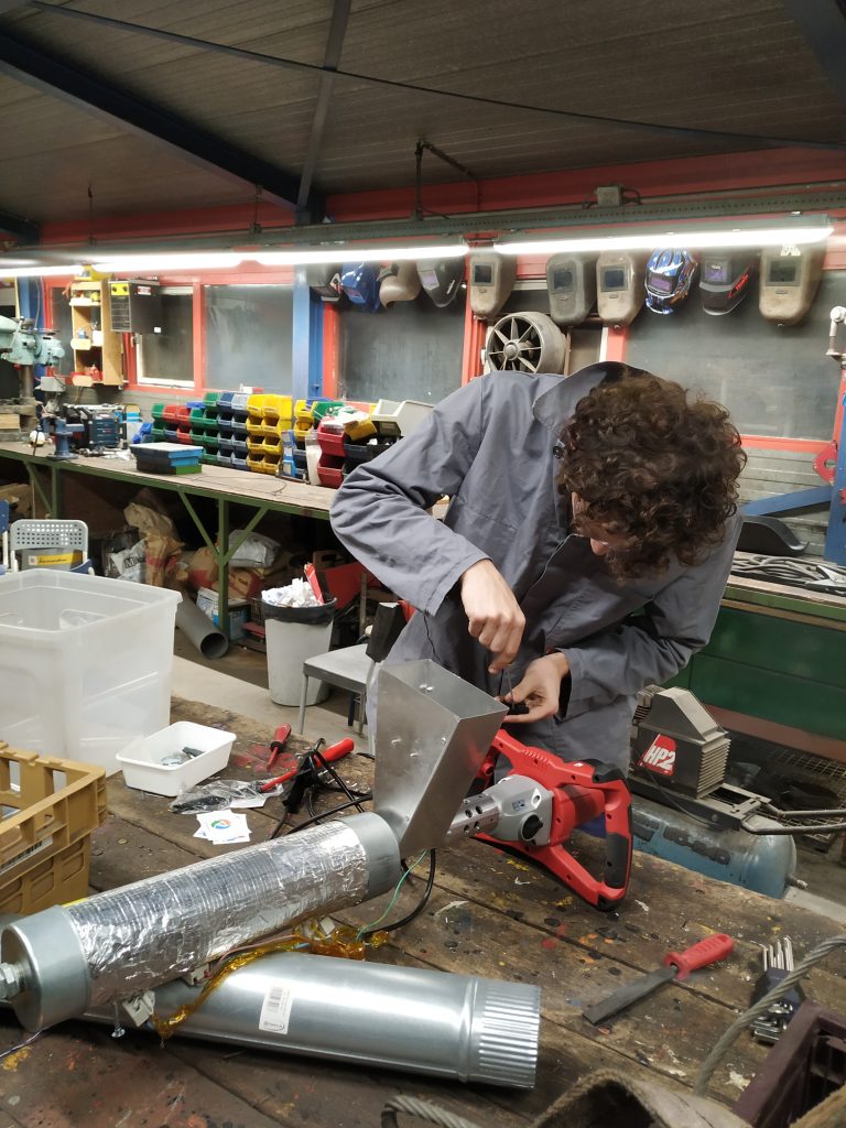
Via HGI the WOT got into contact with Rik Voerman as he had designed an extruder for plastic. This extruder was made such that it would be easy to transport so that people in remote locations can use this machine. It uses a cement mixer that drives a wood auger, while plastic is heated with electrical heating elements. The machine extrudes a lump of plastic that is placed in a mould and pressed together. The extruder does not inject plastic into the mould under pressure as this would require more power and a bulkier setup. The machine is fed plastic pallets or agglomerated plastic film (film made into clumps). Foil is not picked up well by the screw and cannot be processed directly, even if it is shredded.
At the WOT we decided to build this extruder for ourselves. Rik supplied us with the necessary components which were assembled and a simple mould to perform tests with was made on the lathe. The extruder worked well, the molten plastic was deposited in the mould and the mould was closed in a vice. The results were as desired, and the machine was simpel to operate.
Challenges ahead
The extruder performs well at melting and mixing the plastic and it was easy to use. It seems to be a better option for melting plastic than the oven that was made. There are a few things that could be improved however. First of all the extruder is made in the Netherlands and shipped abroad, as it requires advanced machinery to produce. This raises questions about what happens if the machine breaks down, can it be fixed locally? Possible failure and the possibility of fixing the machine will be investigated.
Also the processing of film is difficult, while a significant portion of plastic waste is film. Shredding and agglomerating it is possible, but agglomerators are generally heavy machines that need a very large power supply. These machines may not be accessible to small businesses in developing countries. Research will be done to investigate if it is possible to agglomerate plastic with a smaller machine that requires less power. Also the shredder should be further improved to reliably and quickly shred plastic foils.
Another solution to this problem would be to study what happens inside the extruder and investigate whether the design can be changed such that it accepts film directly.
The further progress of these projects will be posted on this website.
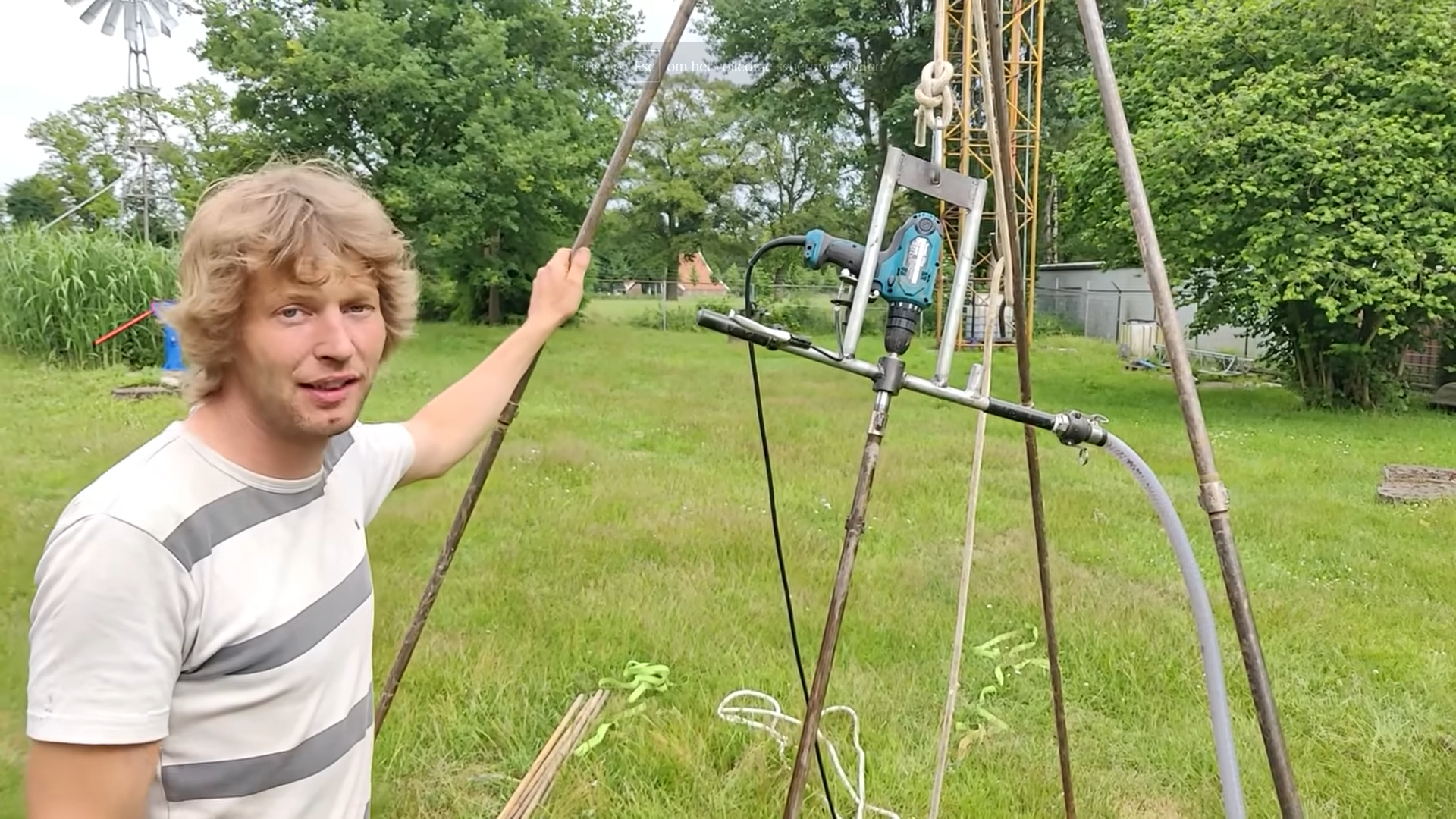
A new youtube video has been published on our youtube channel.
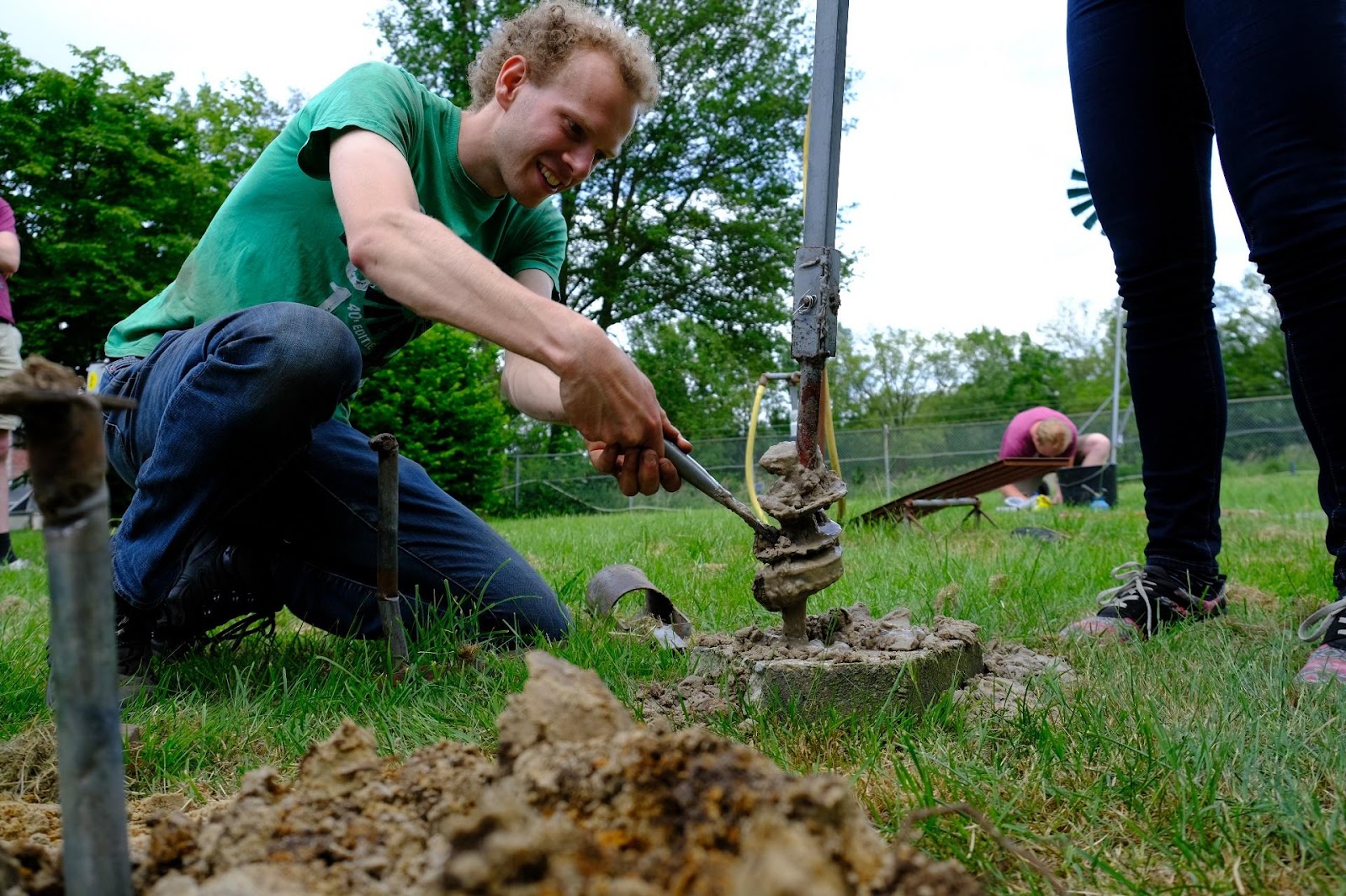
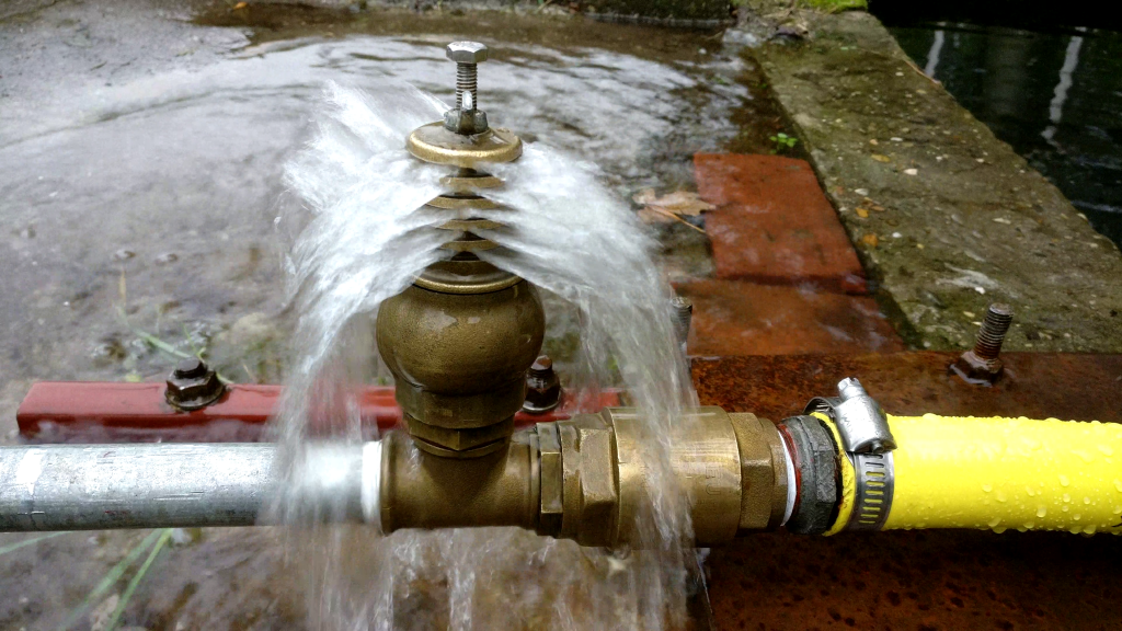
The video shows a custom made well drilling method called rotary jetting. It combines a rotating drill head with a water jet. If you are interested also have a look at the experimental setup of airlift drilling and the motorised airlift drilling setup.
You can watch the video below. Don’t forget to also have a look at the other videos at our channel
The WOT will host introduction activities every Wednesday and Thursday this September. You can sign up for these activities using the following google form: Sign up via Google Forms
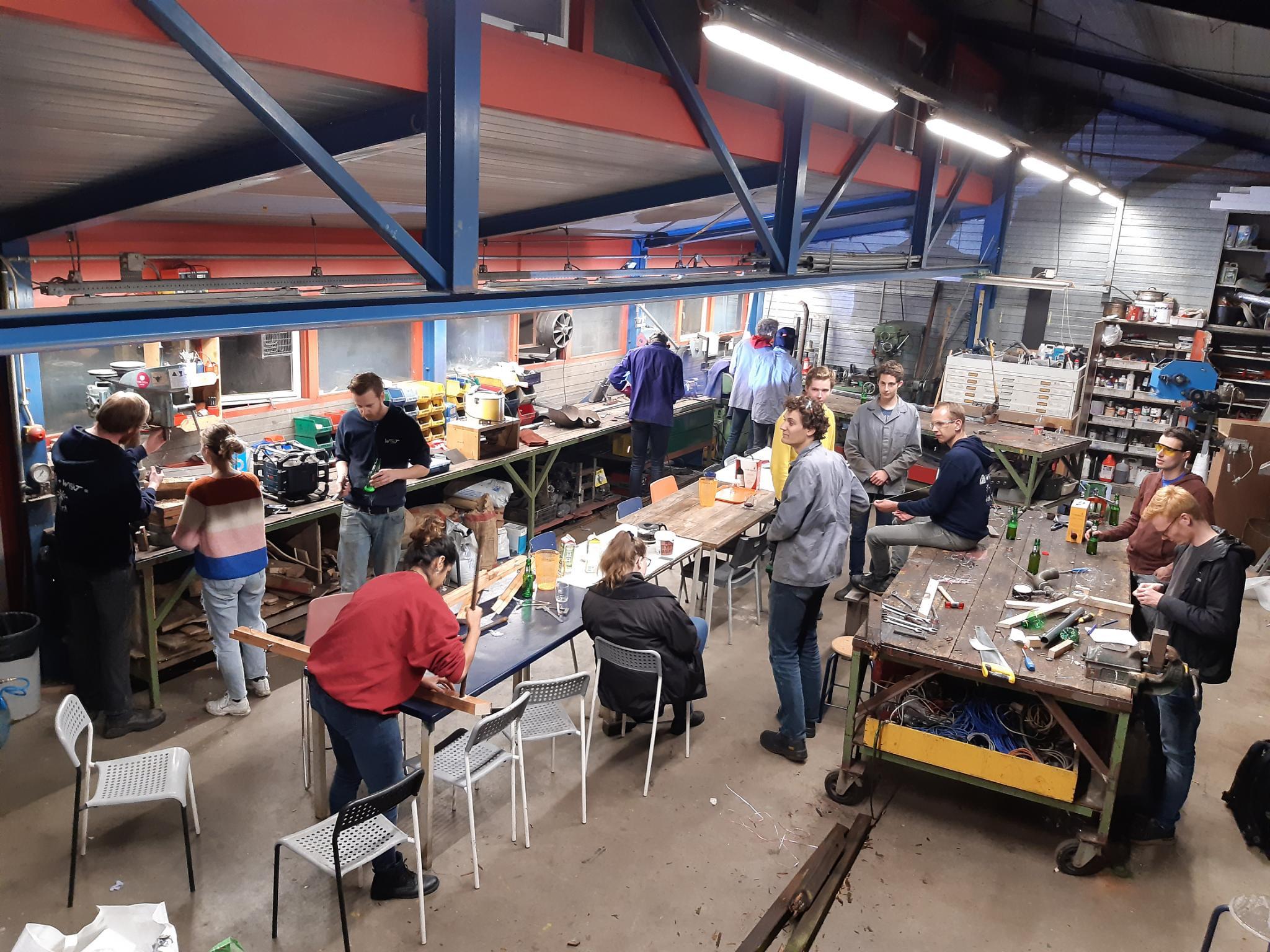
These activities will be organised like our weekly association nights (normally every Wednesday) so we’ll gather at the wot around 17:00 and have dinner at about 18:00, afterwards we would normally work on our projects and end the night around the campfire, but for this introduction period we have some activities planned.
-Wed 8 Sept,
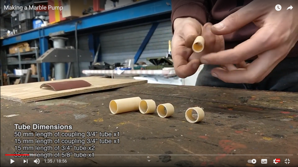
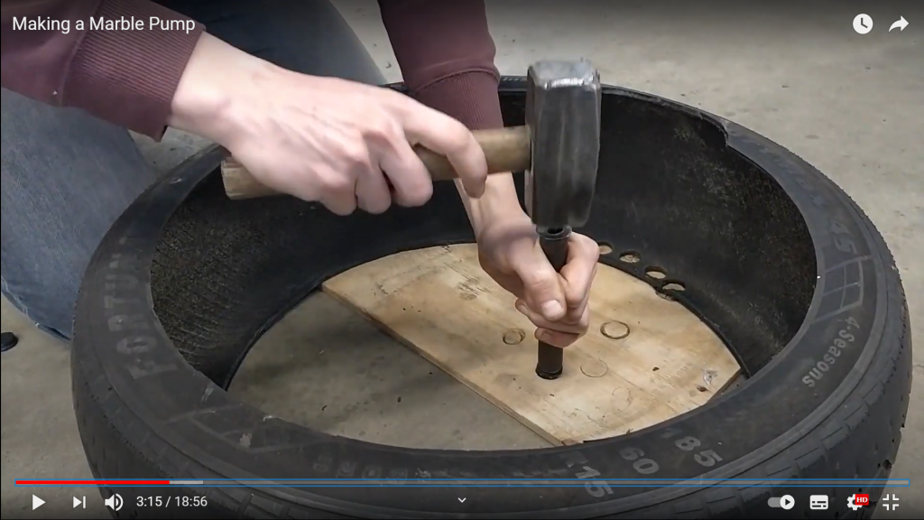
Introduction evening, we will give tours of our terrain and workshop and we will be making marble pumps *A manual for the marble pump (you don’t need to prepare anything) can be found here.
-Thu 9 Sept,
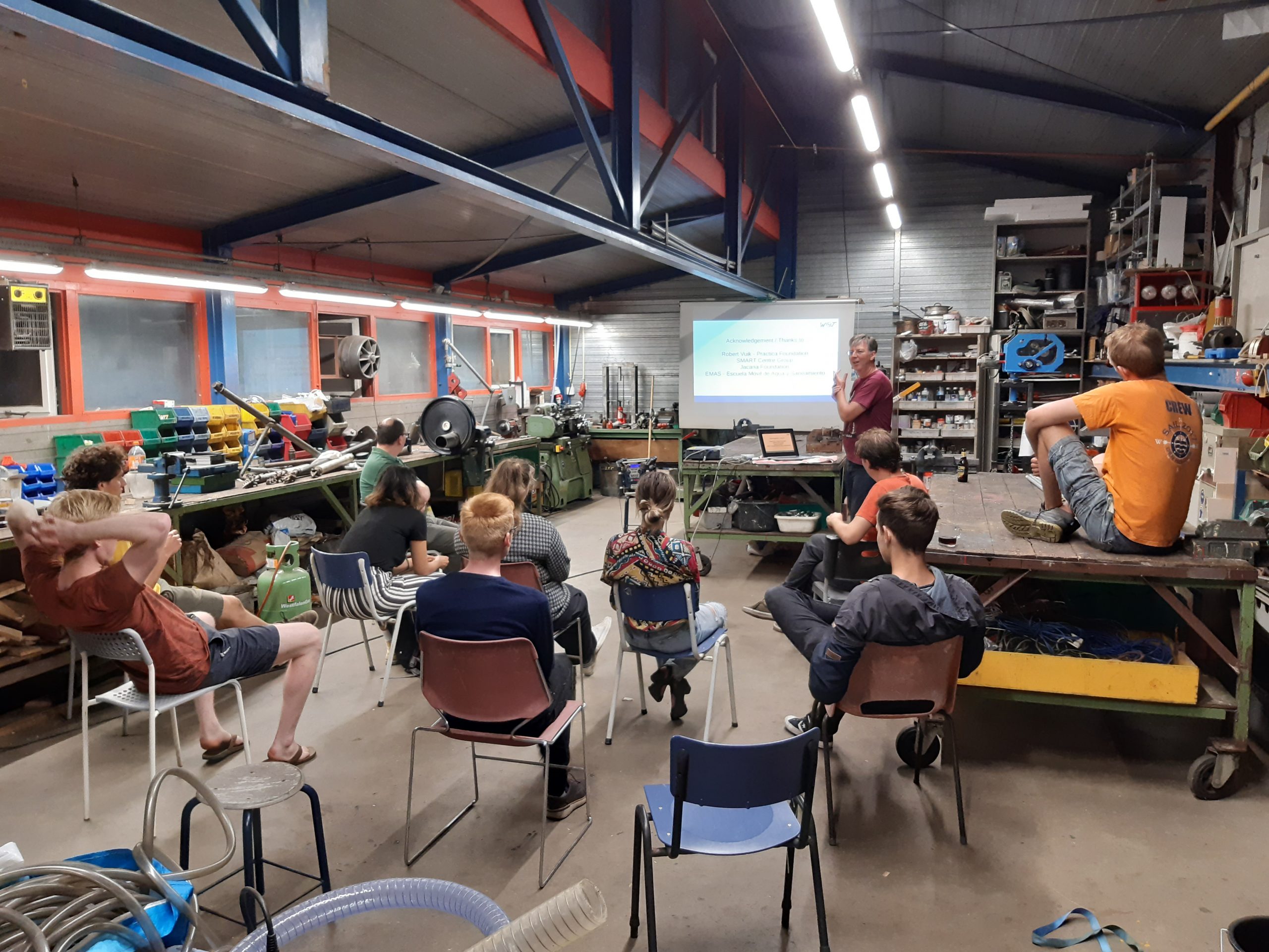
We will host a lecture on well drilling (using manual methods that can be used in development countries), and of-course if you missed the tour on Wednesday there will be an option to be introduced to the terrain.
A lecture on manual drilling methods (2021)
-Wed 15 Sept,
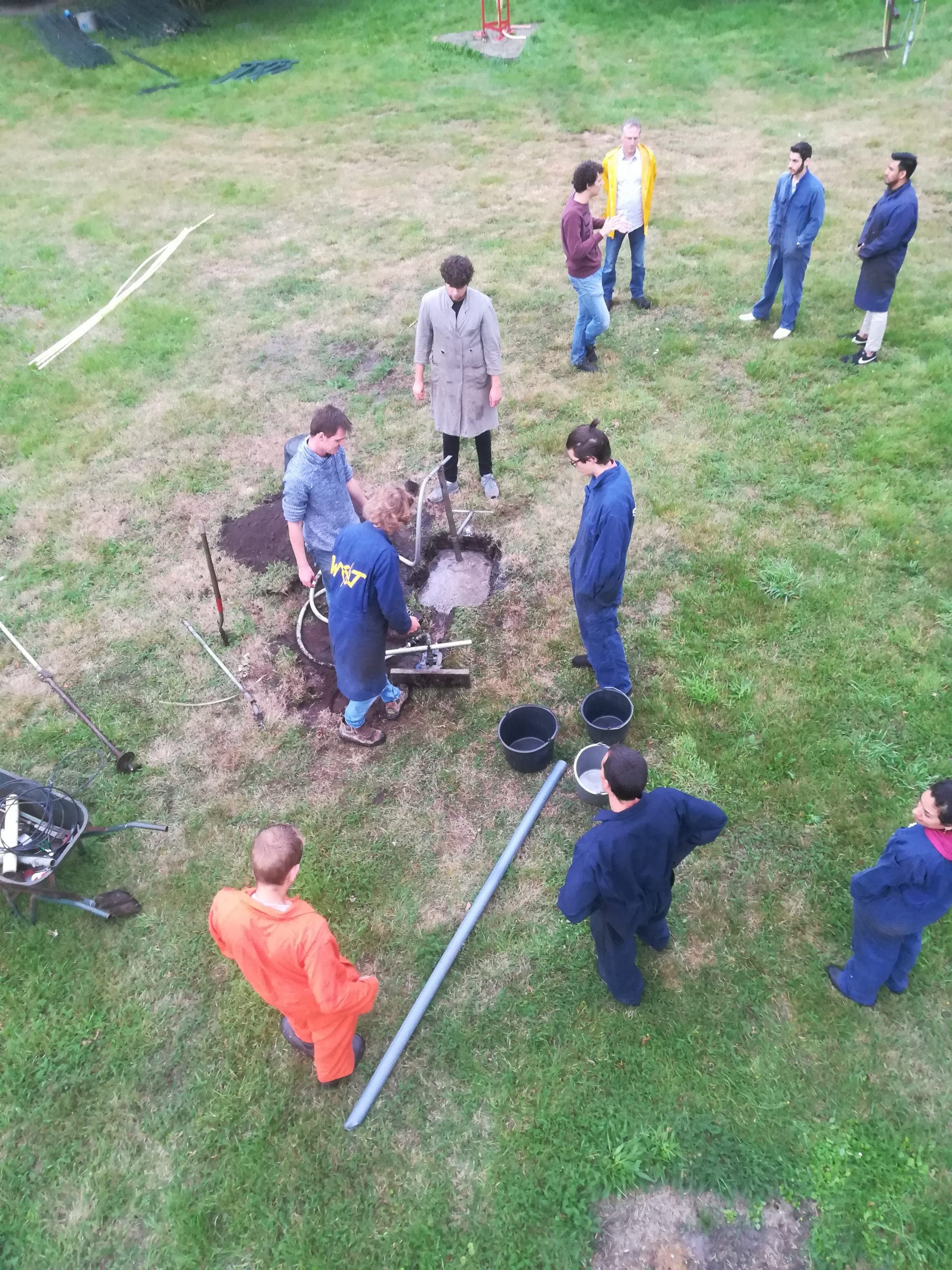
After the well drilling lecture of the previous week we will now actually drill a well using the “Mzuzu” or the “Emas” method.
*these methods will be introduced and explained in the lecture on Thu 9 Sept.
Drilling a well (2020)
Emas drilling (2021)
-Thu 16 Sept,
We will host a presentation on some of the wot’s most prominent projects from the past and discuss our various currently ongoing projects afterwards we will split up into groups and work on some small projects around the terrain.
-Wed 22 Sept,
We invited happy green islands to host a lecture on low-tech plastic recycling techniques. Two people from happy green islands came to the wot and presented their work and goals, they showed us the website ekoMaluku and discussed technical innovations to localize plastic recycling (so it can be done on small islands).
-Thu 23 Sept,
We will divide the group into teams to play a pubquiz on mostly wot related topics (development techniques, climate, mechanical engineering etc.)
-Wed 29 Sept,
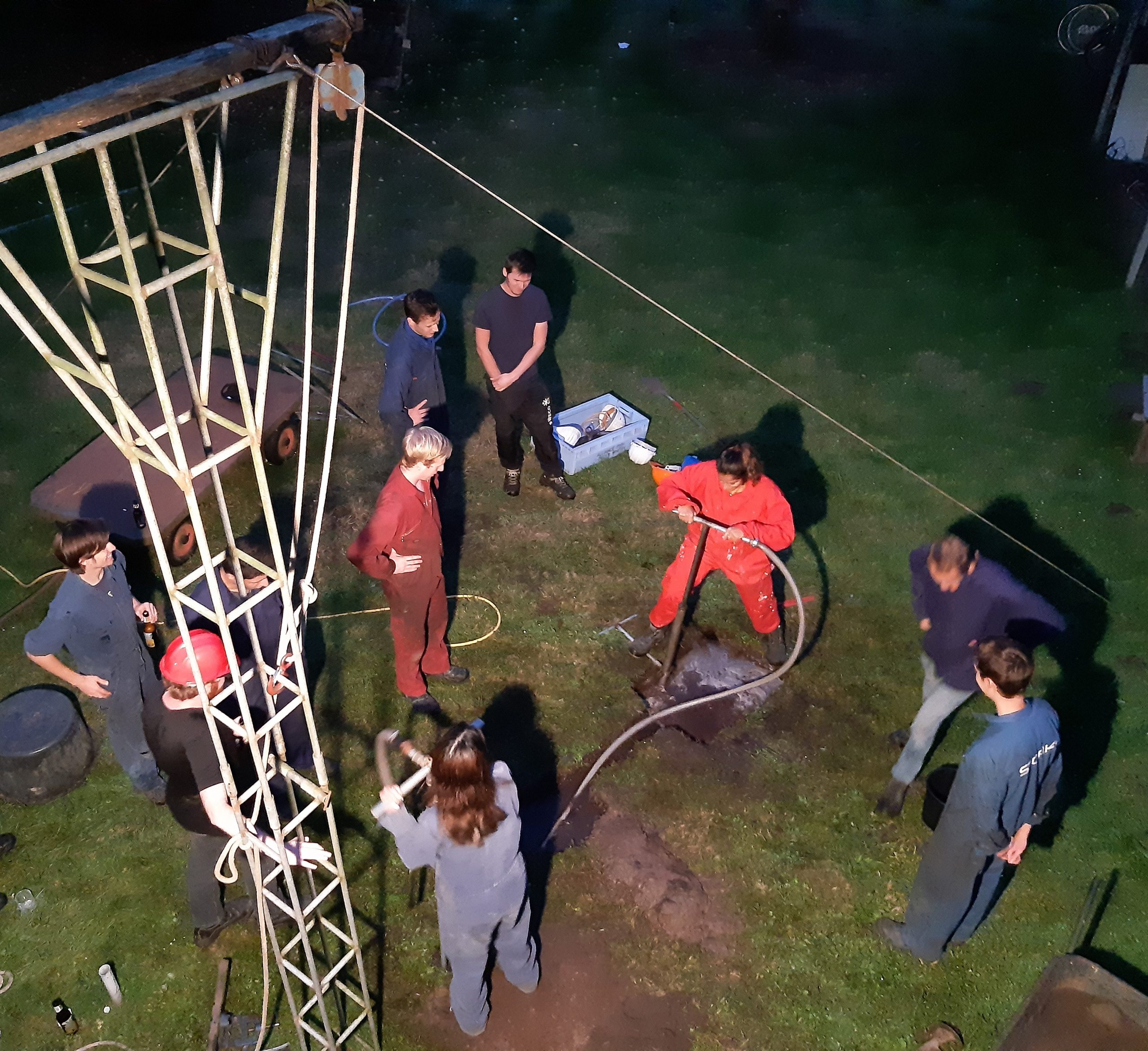
We will continue working on small projects and there will be the change to get involved/help out/watch over some larger projects.
Working on small projects (2021)
-Thu 30 Sept,
We will be giving workshop courses to our new members to introduce them to and familiarize them with the various machines and tools in our workshop. (Welding, grinding etc.)
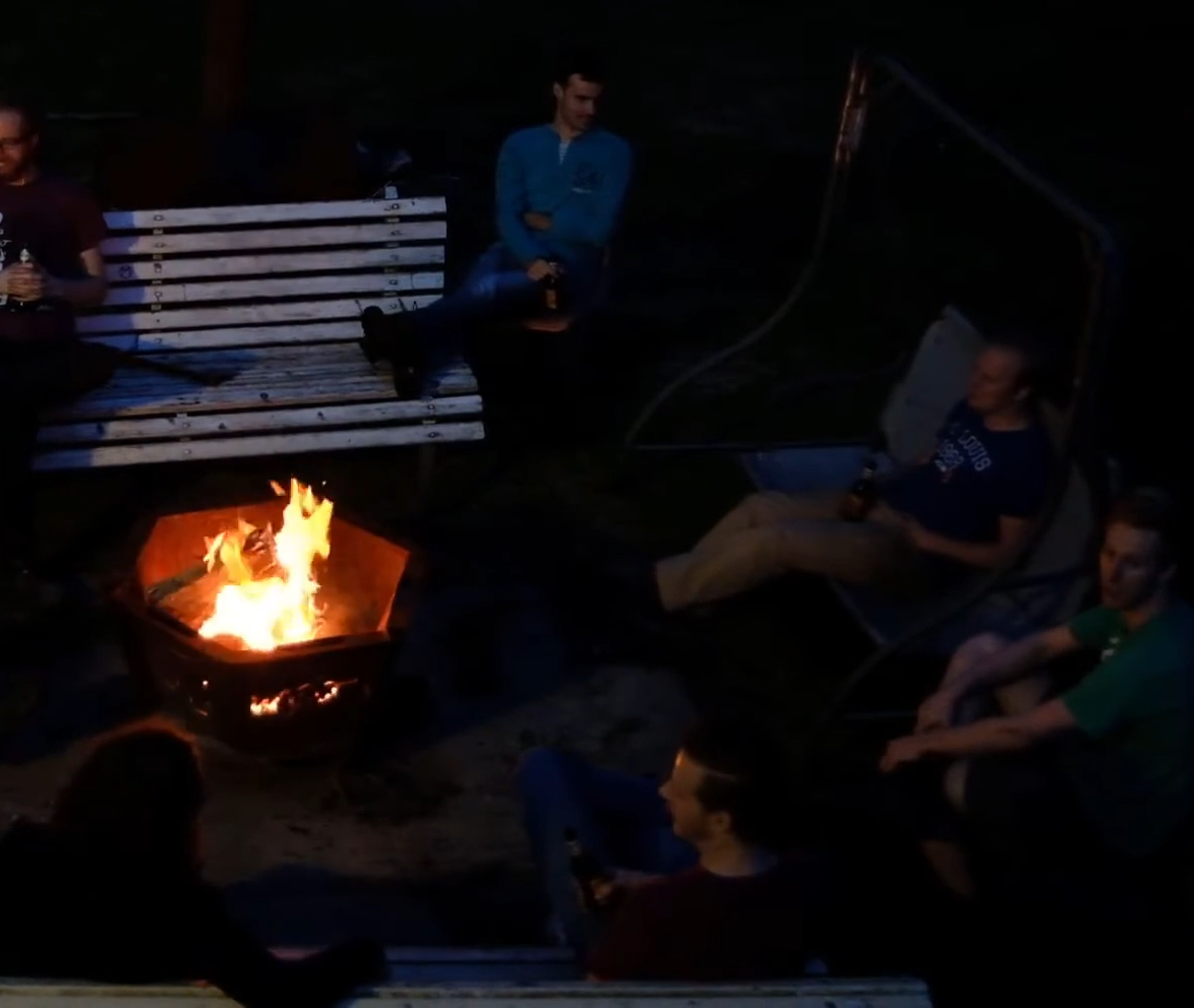
On all these days we will be eating together at the wot, and ending the night around the campfire.
Ending the night around our campfire.
You can sign up for these activities using the following google form: Sign up via Google Forms If you have any further questions please don’t hesitate to contact us. Want to have a better overview of the wot from the comfort of your couch? watch this video that we made last year: https://www.youtube.com/watch?v=EAGf125aG0I *The dates and activities at the end of the video are outdated.
This June, the WOT organized its first physical activity in a long time! In light with the start of producing a Mzuzu well-drilling set, Henk Holtslag from SMART introduced enthusiastic WOTters to the Mzuzu drilling method in a 1-day course.
With regard to an information request on drilling holes through small rocks and thin layers of stone by the Afundisen foundation, the WOT will built and test its own Mzuzu drill set, suitable for this purpose.
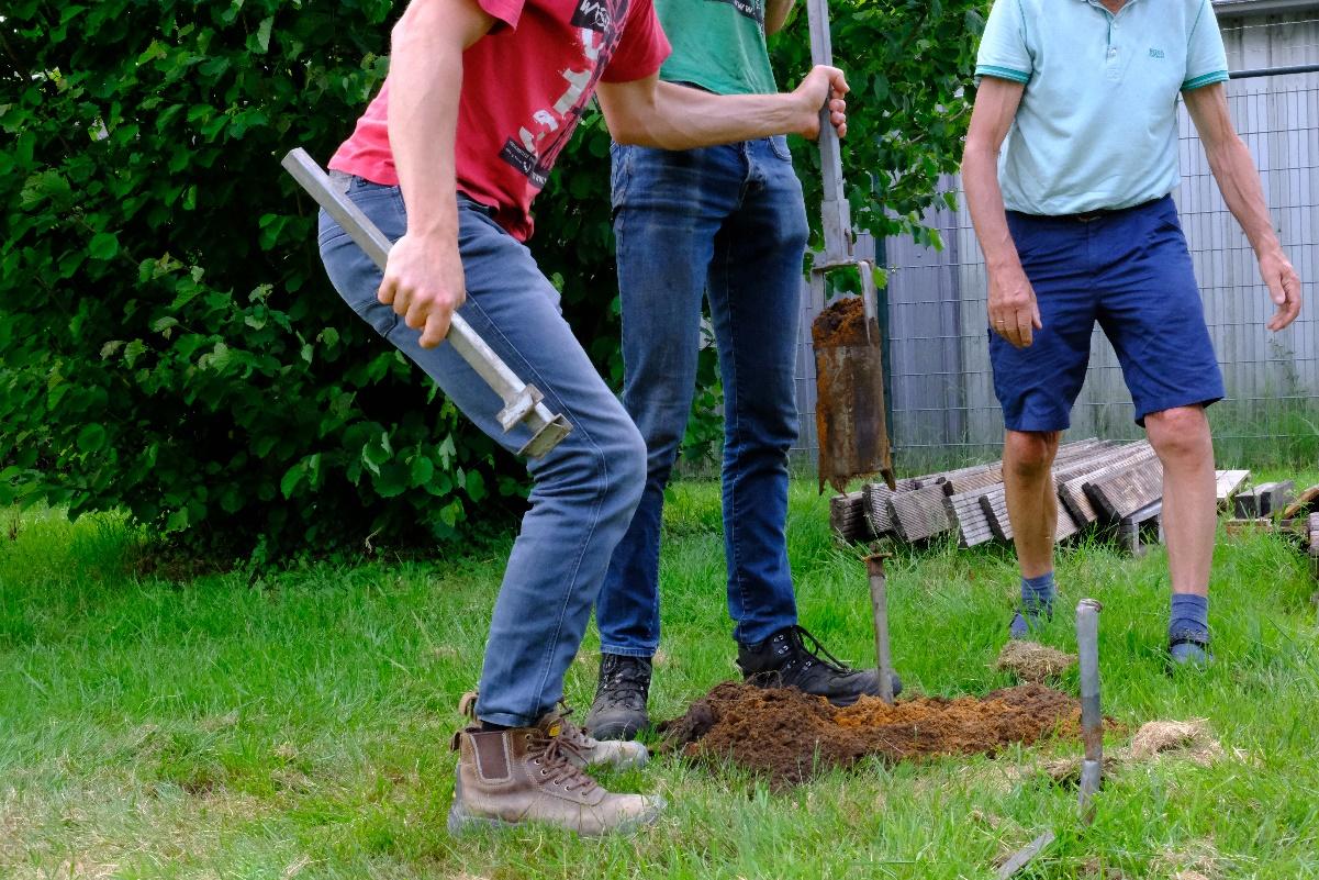
Core auger in action
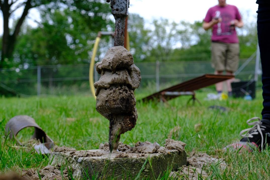
The method consists of 3 different kinds of drill bits and a bailer. Drilling the well starts with the core auger, drilling through layers of loose dirt and clay. The auger can be emptied by pushing the contents on a stick dug in the ground. The drilling speed in this process was about 8 meters per hour.
Once the dirt becomes too wet to use the core auger a spiral auger is used, which is cleaned using a special tool to fit in the spiral. Drilling speed was difficult to measure, but a lot lower compared to the core auger.
The spiral auger in use
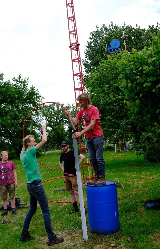
Once the mud becomes too viscous for the spiral auger a bailer is used. This bailer is used within the well casing which will sink deeper into the ground by applying some weight while using the bailer. This is different from other drilling methods which generally place the casing after drilling has finished, using drilling liquids in the process to support the well during drilling.
Start of bailing
The bailer that is used acts as a small bucket with a valve at the bottom, filling with sand by a vertical pounding movement. The bailer is suspended in the well casing on a flexible pipe and is emptied using a bucket of water. Once more drilling speeds were difficult to measure, but were even slower than while using the spiral auger.
As a last part the bottom of the well is sealed by dropping a small plastic bag filled with cement into the casing.
During drilling with augers a stone punch, fixed on the same pipe as the two augers, can be used to disintegrate small rocks and thin layers of stone to reach the water aquifer. However the soil on the WOT terrain contains neither, so this has not been practiced.
A big thank you to Henk Holtslag for displaying the Mzuzu drill method to the members of the WOT! Once we have finished building our own Mzuzu drill set we will start with more tests to get experienced and find more accurate drilling speeds, depths and the possibilities of using a stone punch.
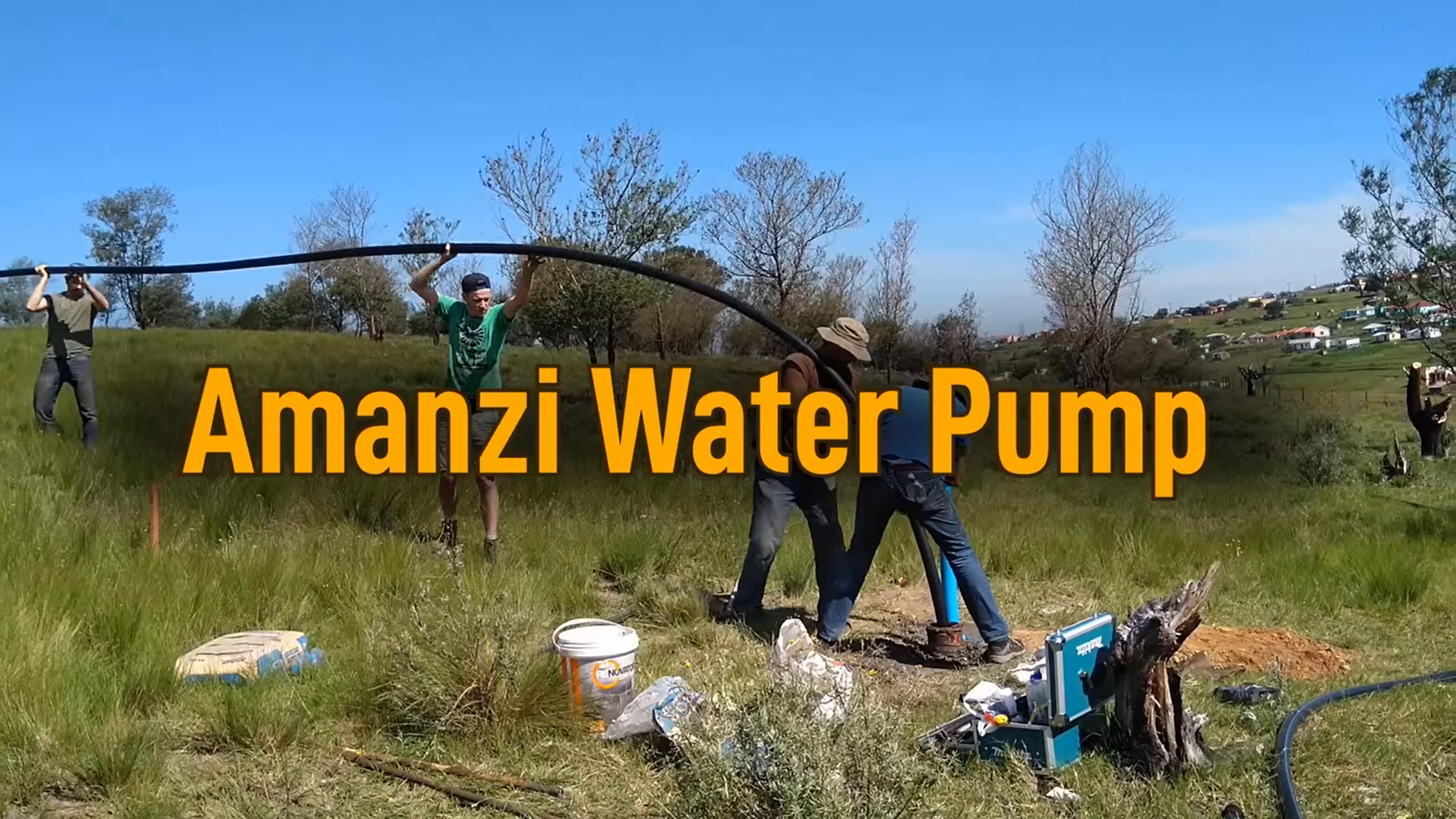
A new video has been posted on our youtube channel. The video shows how to construct an amanzi water pump. This is a pump made from HDPE pipes. Therefore it is flexible and lightweight.
You can watch the video below. Don’t forget to also have a look at the other videos at our channel.
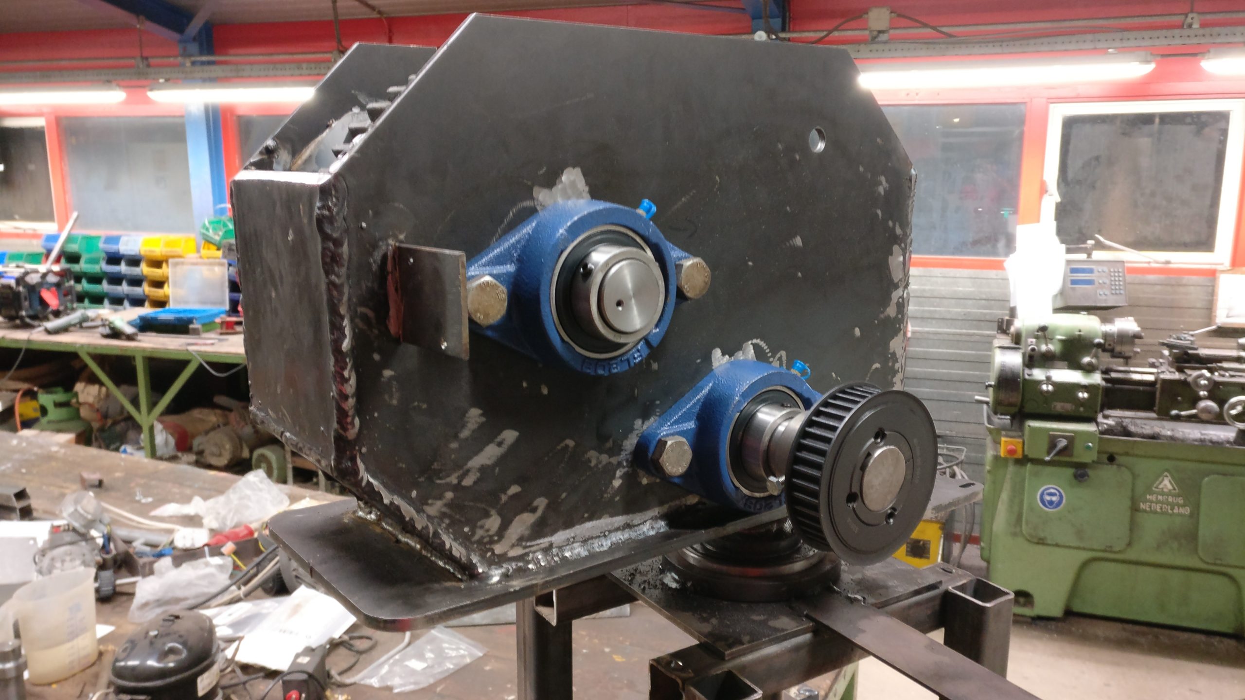
Since the last post about the new windpump gearbox a lot of progress has been made. In this blog, we will discuss some of the findings during the process. Also, some important changes are made to the design which will be discussed. Starting from the last blog post about the gearbox the test installation is finalized from the first design.
Bearings
One of the first major changes to the design is the type of bearing used. At first normal bearings are used for which a housing is made and welded to the gearbox casing. As could be expected the alignment of the bearings was rather difficult. When the bearings were installed it was not possible anymore to change the distance between the two gears.
Both problems are solved by making use of flanged bearings which have a couple of advantages:
Easy to replace.
Axle can be fixed in place, so no additional parts are required.
The ability to compensate for some misalignment.
First run
In the video below the first rotations of the gearbox are shown including the counting of the strokes. The transparant window is only for inspection purposes during the test phase of the gearbox.
Now all the main components are working the gearbox is painted and the last details are worked out such as preventing the weight from rotating during yawing.
Steel cable
At first a steel cable is used to transfer the rotating motion of the rotor into a translating motion. A 6mm thick steel cable is used, however this cable snapped after 59.535 strokes due to the small pully (60mm diameter) used to guide the cable. According to the steel cable manufacturer, a pully of a steel cable should have a minimum diameter of 20x the cable diameter. This would result in a pulley with a minimum diameter of 120mm, within the gearbox there is no space for such a pulley.
A smaller steel cable of 4mm in diameter is used in combination with a slightly larger pulley (85mm). This cable snapped after only 19.334 strokes, a final test is done with the 6mm cable in combination with the larger pulley. This helped a bit, however the cable still snapped after 69.591 strokes.
Another problem with the steel cable is that if the tension by the weight is released it will immediately ‘jump’ of the guide pulley. Whenever the gearbox is started after that the cable is damaged, which is not preferred if the gearbox is up a windpump.
Solution: Instead of the cable, a chain is used in the newest improvement of the gearbox. This new configuration has done over 120.000 strokes without problems.
Test results
Based on the previous blog post about the gearbox several things where tested and monitored during the manufacturing and working of the test setup:
Effect of yawing on the cable: The weight is fixed and cannot rotate as we expect that the cable/chain will fail before the pump starts rotating in the borehole. Therefore a coupling is made which will account for the yawing motion of the windpump head. This connection can also be used as a safety feature if the pump will get stuck in the borehole for instance. –> this coupling is working well and will be discussed in a later blog.
Ease of manufacturing: As discussed before, alignment of the bearings appeared to be difficult. With the new flanged bearings, the tolerances on the different shafts can be less precise.
Oil consumption: Oil will leak through almost every hole present in the gearbox, so the correct type of seals have to be used where the axle goes through the gearbox housing and where the gearbox is bolted to the tower head. Most of the oil will leak via the cable/chain through the tower pipe if the cable/chain is touching the main gear. This can be easily prevented by making the gearbox housing a bit bigger.
Failure modes: The main failure mode appeared to be the snapping of the cable, this is solved by using a chain instead of the cable. To find more failure modes the gearbox has to be tested with contamination like sand and water from outside the gearbox.
Maximum load: The maximum load and the weight of the weight is not determined yet. It is assumed that the maximum load is currently limited by the motor simulating the rotor.
The Breurram is a type of waterram pump that was developed by a WOT volunteer in the 90s. There already is an elaborate manual on how it works and how to build one. In addition to this we decided to make an instructional video about this great pump.
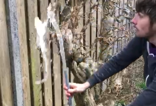
The video shows the pump in action, it explains how it works exactly and a timelapse of the assembly process is made. Also the yield of the pump at different heights is shown.
For more information about the Breurram please go to this page. The manual you can find here in multiple languages.
As WOT members we love making things playing around with all kinds of different tools and materials, since we are not able to collectively do that at our terrain we decided to do it separately.
For this reason we organised the Epic challenges every week we work on a different small project.
-Challenge #3 For this week’s challenge members were asked to create an instructional video to explain how to build a marble pump. The video of the winning team would be placed on the youtube channel of the WOT.
Only two submissions were entered and since they both elaborated on a different type of design, it was decided that both videos would be put on the Youtube channel. You can check out the video’s at our youtube channel: https://www.youtube.com/channel/UCD9iM7XU_iuZWsFQ9A_F2kg
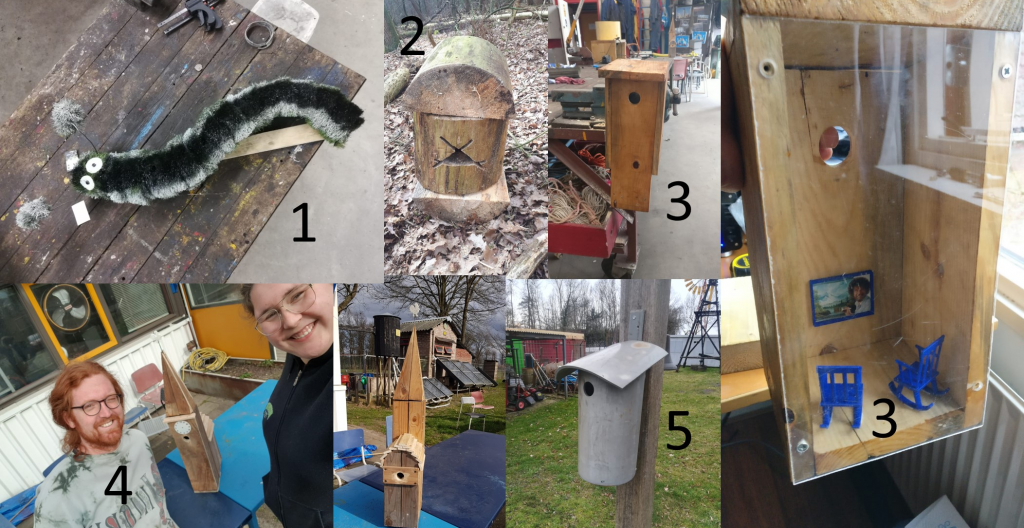
-Challenge #2 We are making bird houses, but not just any bird house contestants are encouraged to make their birdhouse as comfortable and luxurious as possible, and of course creativity and originality are very welcome in this mini project.
On Wednesday 10-3-2021 we voted and birdhouse #3 won, of course hugely due to the Bob Ross television, now we just have to wait and see if the birds like our creations.
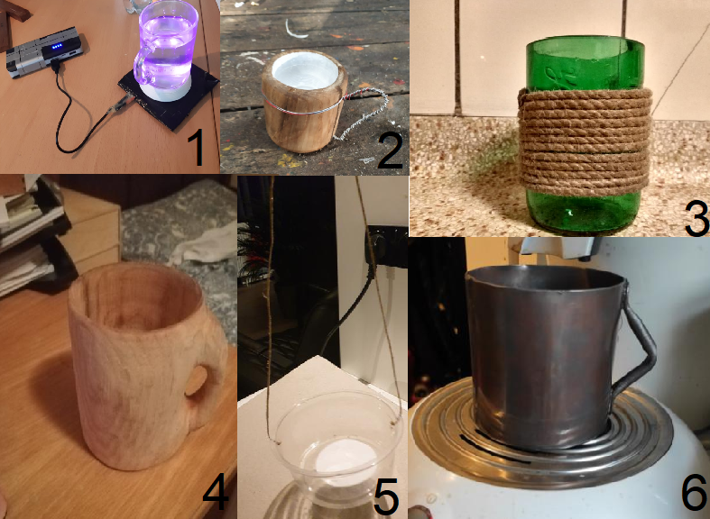
-Challenge #1 Contestants would fabricate their own unique coffee mug to be used in the kiwanda, for this members used all kinds of techniques, from electroplating and welding to turning and 3d printing. These are some of the resulting mugs that where produced:
On Wednesday 3-03-21 we voted to determine the winner, and although it was a close call mug #4 won! A mug shaped out of wood using a lathe, a chisel and probably quite some time.
As a duration test the plastic pump system which is currently tested at the WOT is placed under the Kjito windpump in the second half of 2020. During the last couple of weeks the pump was struggling with pumping water, only delivering during high wind speeds. This made the foot valve the suspect of the problems. However, during the period of low temperatures of the last couple of weeks all the windpumps where shut down to prevent damage due to freezing of the pipes. This gave a opportunity to remove the pump from the Kijito and investigate the pump in more detail to find the actual cause of the problems.
Kijito well
The well under the Kijito windpump consists of a well which is dug out. The sides are reinforced with concrete and there is no bottom in the well which makes it dependent on the level of the ground water. The well is around 4.5 meters deep with at the moment (February) water at 2.5 meters. During summer and high winds the well be pumped empty which is not good for the longevity of the piston.
Cause of the problem
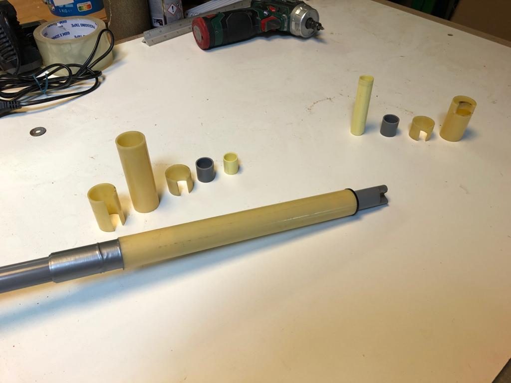
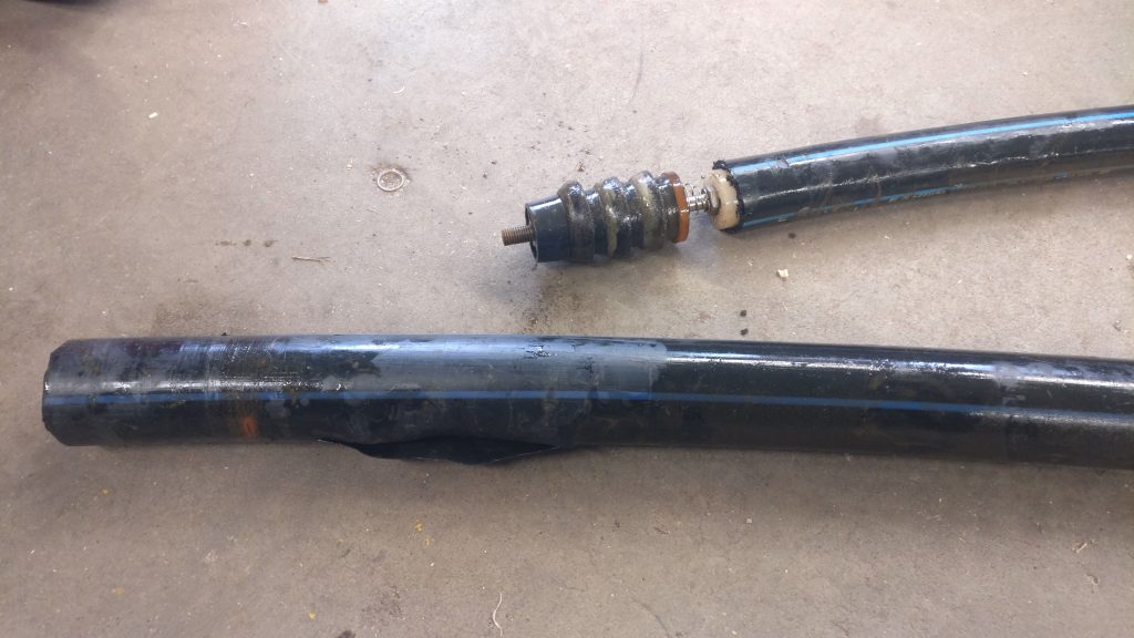
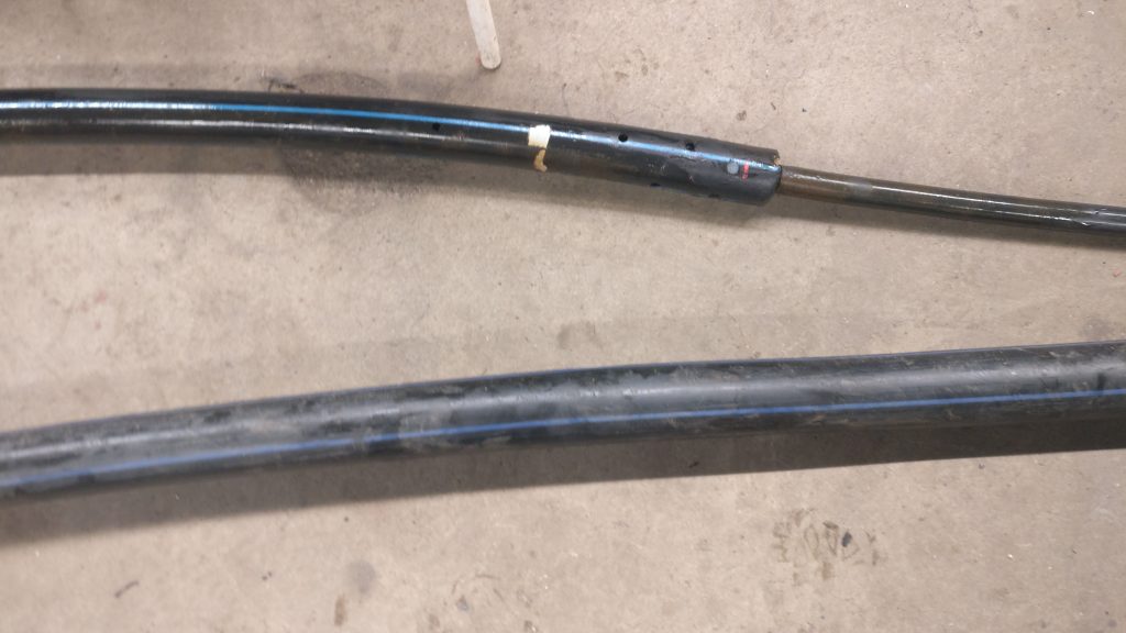
As mentioned above the pump showed signs of a bad foot valve, however the foot valve was in great condition! the part that failed was the outer pipe of the pump, the piston had so much friction that the wear on the pipe was so big that the wall thickness decreased resulting in:
First pressure point (teared wall)
Second pressure point (worn down wall)
It is remarkable that this problem occurs only after a couple of months. This pump design is already used for multiple years without maintenance in South-Africa. However, the main difference is the well or borehole used. The boreholes in South-Africa are mainly 10″ holes of tens of meters deep, sometimes even over 80 meters deep. These deep and narrow holes force the plastic tubes of the pump to be straight and therefore easy operation.
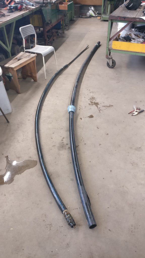
The well of the Kijito is very shallow and wide compared to these boreholes. This results in the tube not being straightened properly and therefore creating two point of high pressure on the outer pipe (at the point of the piston and where the inner tube changes to the solid plastic rod). When the pump was removed from under the windpump the tubes where still not straight:
Solution
Since the cause of the problem is not found in the design of the pump but the way the materials are used, the most important lesson to be learnt is: Make sure the pipes are straight. In case of the Kijito well, which is shallow and wide this is not a straightforward job. For now there will be ordered a new outer tube and a way to straighten out the the pipes will be found.