During the last working weekend at three and four october progress has been made with the new gearbox design test setup.
This new gearbox design has a couple of unique features for windpumps which have a gearbox between the rotor and pumping rod (to slow it down and increase the pumping force). These type of wind pumps are widely used in South Africa. The following text is from my internship report on the design of a new wind pump which was mainly focused on the rotor but also adresses the gearbox shortly:

Gearbox of a Climax windpump
To ensure starting at low wind speeds and deep boreholes a gearbox is needed in these wind pump. Together with the new rotor design a new gearbox was designed which is simple in design and can be maintained easily.
Current gearbox design’s like the Climax and Southern Cross windmills consist of cast iron housings which cannot be welded when broken. Furthermore, there are two sets of gears which have to be synchronised to work properly. The use of solid pumping rods leads to ’knock’s’ in the gearbox which are described in the instruction manual for southern cross.

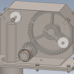
The new gearbox design
These knock’s are caused by the speed of the pumping rods during the upward stroke. The rod pushes the gears up which results in knocking over of
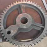
the gears. To prevent this a gearbox with cable is designed since a wind pump doesn’t have to push the pump down in normal operation. To make sure the pump rods will go down springs are added to pull the rods down. Furthermore, only two gears are used with a ratio of 3.2 : 1 which requires 3.2 rotations of the rotor to perform one pumping stroke. The casing consists of welded sheet metal instead of cast iron to make it possible for people with a welding machine to repair it themselfs.

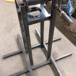
Experimental setup
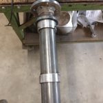
Since this type of gearbox has never been used before a test-setup is designed to be able to see if the gearbox is working without building a complete windpump. This setup will simulate the rotation of the rotor using an electric motor. The same will be done to simulate the yawing of the windpump. This is expected to be one of the major challenges with this design since the pump will not rotate, but the head of the windpump will. using a stiff pumping rod is not a big deal, but the cable that will be used in this design is not able to resist against torsion. It can be assumed that the windpump will yaw an even amount of times clockwise and anti clockwise, but it is still usefull to know how much rotations the cable will resist without problems.
The bracket around the gearbox is used to make sure that the power cable going to the motor which simulates the rotor rotation doesn’t get strangled up. Furthermore, ball bearings are used as yawing bearings which happened to be quite a challenge to install. So in the final design friction bearings will probably be used since they are much easier to install, allow for less tight tolerances and are more resistant against dust and moisture. But for this proof of concept it won’t affect the results.
Besides this there will be a couple of other things be tested during manufacturing and testing:
- Effect of yawing on the cable
- Easy manufacturing without expensive precision tools
- Oil consumption of the gearbox (how oil tight can it be?)
- Failure modes
- Maximum load
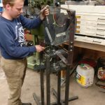
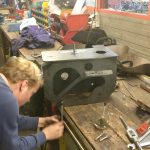
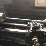
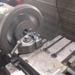
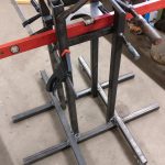
Currently the frame of the setup is tagged together, the gearbox itself is tagged together and the different bearing housings are finished. The big gear is machined, only the teeth have yet to be touched with an angle grinder to make it ready to use. The next step is to manufacture a new ‘rotor’ axle since the current one turned out to be bent. Furthermore, manufacturing of the axle for the big gear which has some tight tolerances.