Posts Tagged ‘water supply’

Working weekend 8 and 9 October

Sunday, November 6th, 2022 No Comments

During this incredibly productive weekend in October, a group of dedicated members came together to work on numerous projects, repairs and improvements. A list of projects including an EMAS cistern and a new electrical system for the Kiwanda was prepared beforehand as to allow the work to start more smoothly. It wouldn’t be long until the sound of digging music filled the field as members got out shovels and spades and got to work. 

Cistern

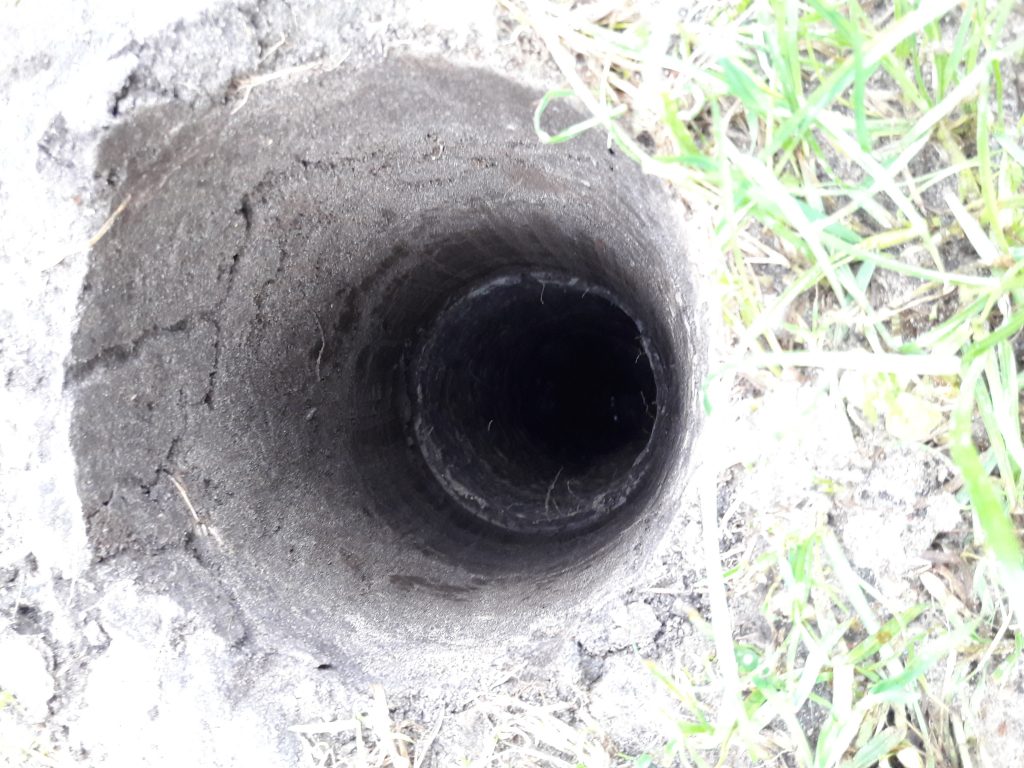
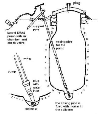
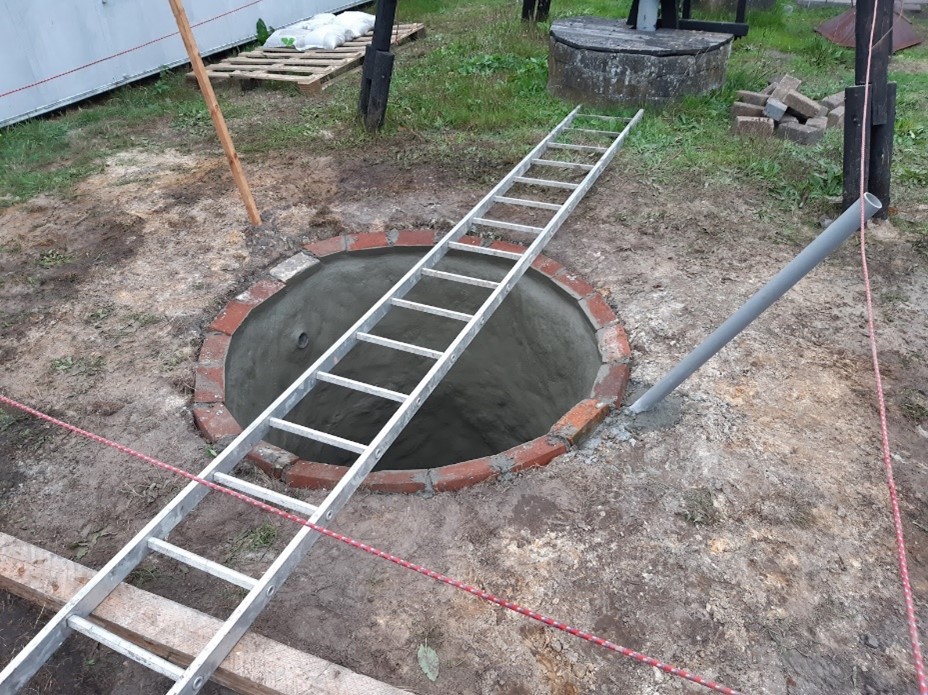
During the working weekend we started constructing an EMAS cistern. The EMAS cistern is an alternative for an above ground water storage, which uses very few materials. As we have quite sandy soil we planned to make the sand variation of the emas cistern in which you don’t make a bottleneck but have straight walls. This due to collapsing hazards of the sand based bottleneck while constructing.
After a morning of digging we had a hole with a diameter of 150cm and a depth of about 230cm. The floor of the cistern has a slight slope with the lowest point at the center. This means that all the water can be removed for cleaning purposes. We then started making the reducerring, which is made out of cement and rebar and plastered the inside of the hole with a layer of cement. The next day we added another layer of cement after which we started painting on a pure mixture of just cement and water to seal the cistern and prevent it from leaking. We also added a layer of bricks on top of the cistern walls to place the reducerring onto. In the weeks hereafter we added another layer of bricks on top of the existing layer and plastered the in and outside of the ring. We then placed the reducerring on top. We are currently working on the first flush system and the appropriate connection to the gutter.
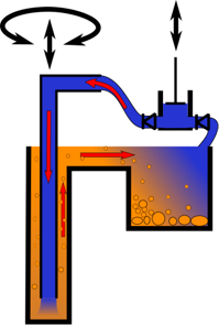
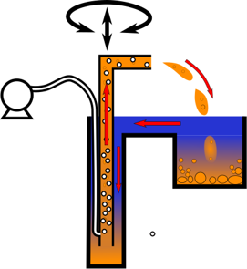
Burgert pump

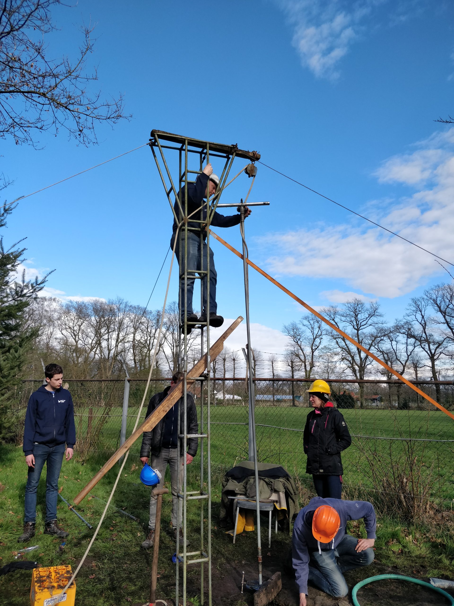
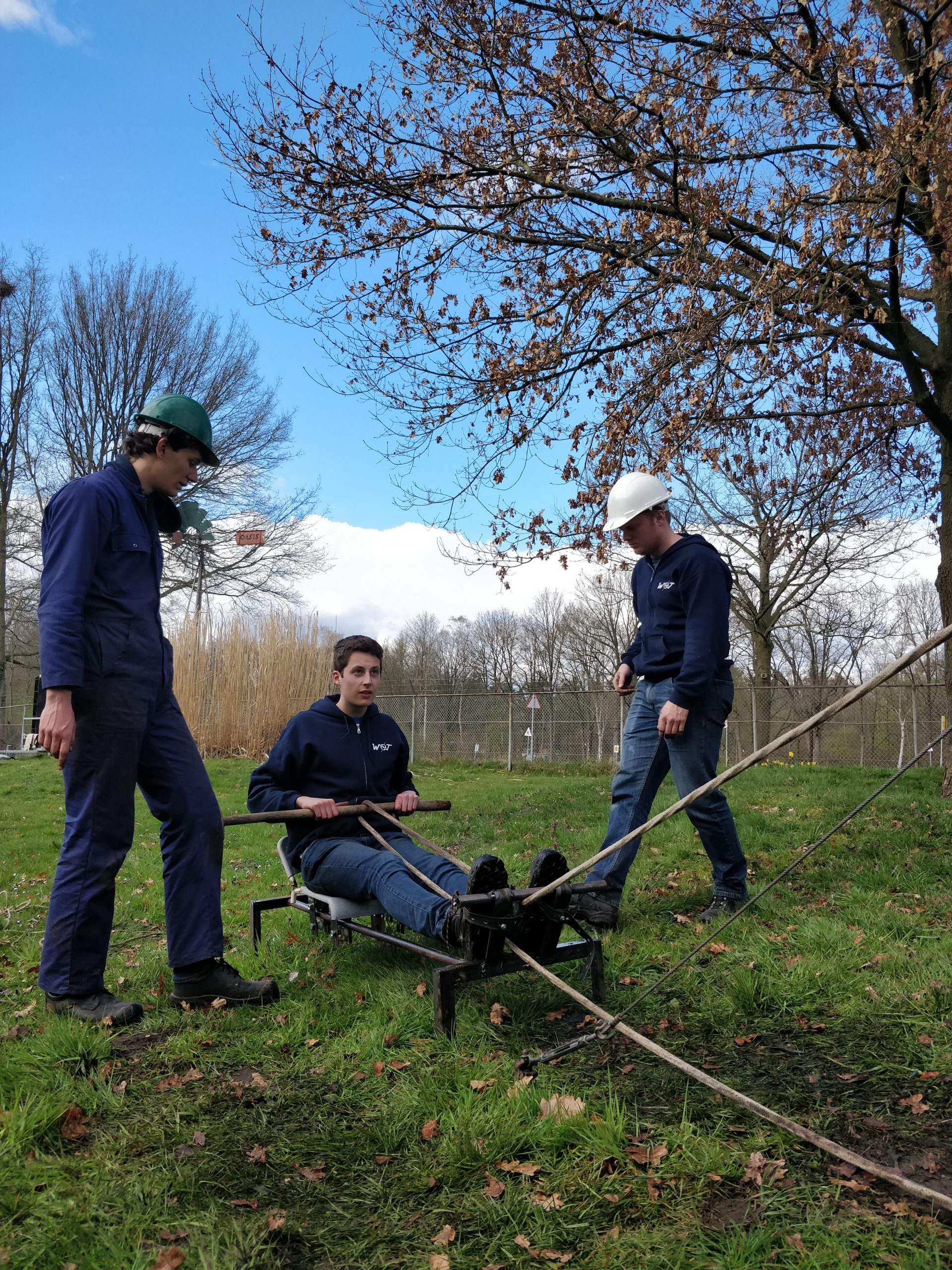
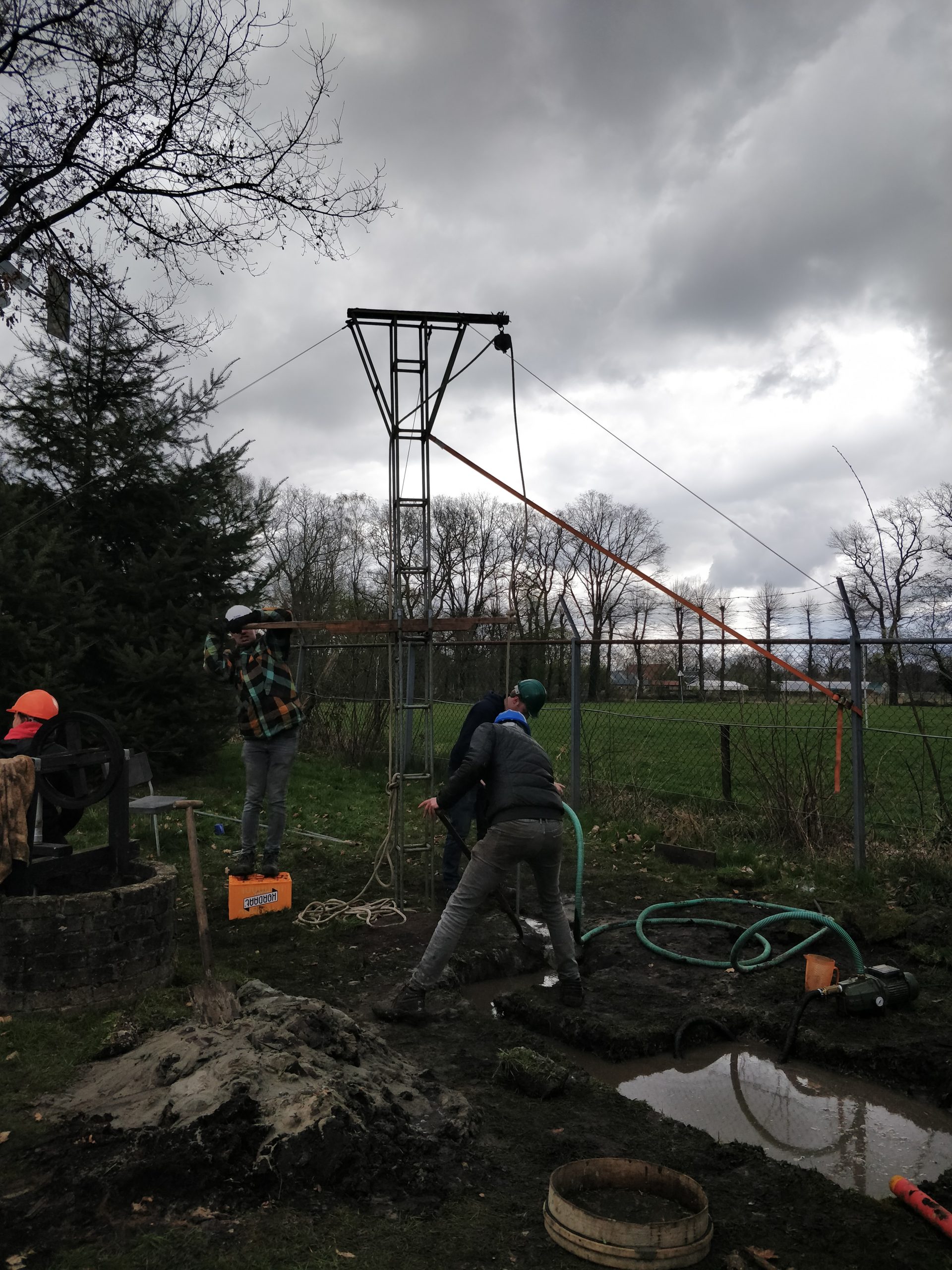
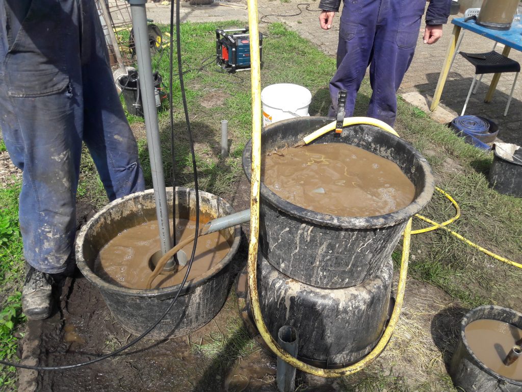
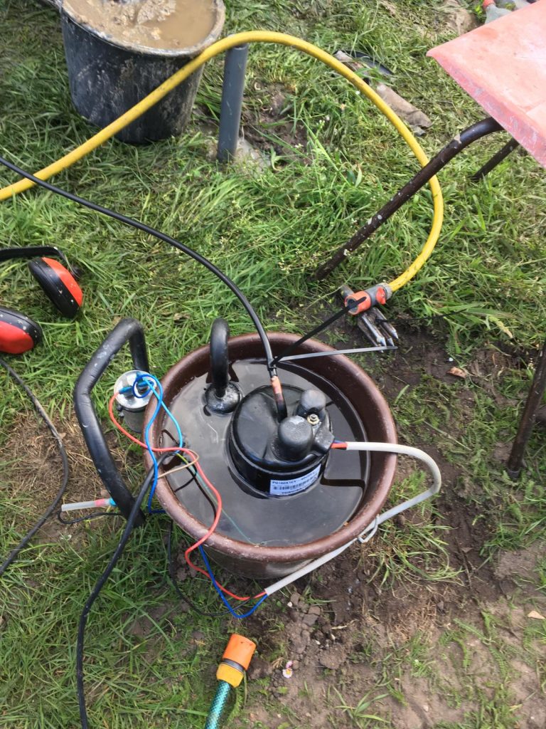
On Saturday morning we started working on installing a new Burgert pump for testing under the PTB. To do this we first needed to move the pump mount under the flywheel which will power the pump during the testing phase. The last time this had to move, a sledge hammer was used to get the desired result. This was problematic, as there was no room to manoeuvre the sledgehammer to knock the pump mount back. To overcome this issue we lifted the hole assembly from the bottom and used al our strength to push it back to the original spot. After it was secured to the frame we started to measure the distance from the current end of the shaft to the water level to determine the length of tube necessary to mount the pump flush with the water and add a pressure gauge. We also needed to extend the connecting rod from the flywheel to the pump. After some adjusting the pump worked and stopped hitting the valve on the bottom of the pump which would have critically damaged it if turned on without adjustment. On Sunday the only thing that needed work for this project was the sensor electronics which keep track of the performance of the pump. This wasn’t finished at the end of the day however, due to some unforeseen issues with the code that runs the microcontroller.

Electrical system

Besides all these projects a start is made on a new electrical system suspended overhead through the middle of the workshop, bringing power to the moveable workbenches. With this project finished the hassle of extension cords and wire mazes will become a thing of the past in our beloved Kiwanda!


Wotters in Kenya

Wednesday, June 1st, 2022 1 Comment

A few months ago, two organisations specialized in well drilling training, invited the WOT to join them in Kenya. They wished to reach more people through a YouTube video of the drilling and training process. Two members of the WOT accepted this challenge and travelled to Kenya in May.

The course was focused on water supply for poorer communities in rural areas. The drilling method is designed in such a way that no difficult or expensive tools must be utilised in the process. The wells and boreholes are often a lot safer and more hygienic than the alternatives present in the area. The training stretched across 3 weeks in which multiple wells were drilled. Water tanks, various pumps and DIY solar showers were also demonstrated. People from all over the country, and even some from abroad, joined the course: a huge success!

Training as such, can be found all over the world. Unfortunately, this specific drilling method is used almost only in Bolivia, where the inventor lives. We hope that, through promotion efforts, the EMAS drilling method can be used more often in Kenya. And that the WOT can do our bit in distribution of said knowledge.

Afterwards we made a video on the EMAS drilling method:


Working weekend 1st and 2nd of April

Wednesday, April 27th, 2022 No Comments

After a long winter we’ve organised our first working weekend of the year! With joint efforts, the main goal was to drill a well at the back of the terrain for the new ‘Umoya’ test-setup that will use the earlier posted ‘new gearbox design’ by one of our members. The well was planned to be 12 meters deep with a diameter fitting for a PVC-tube of 125 mm. This seemed quite a challenge since this diameter has not been tried before on our terrain. However, with our EMAS drilling tip extended and filled with good hope whilst wearing warm clothing, we set to work.

Throughout the weekend some of our members posted stories on our new Instagram page to show to the outside world how the EMAS drilling method is used to drill a well and of course to show part of what we do as the WOT. So if  you do not do so already, be sure to follow us on Instagram! A big thank you to all members who worked on the Instagram stories!

In one Saturday we managed to drill to 9 meters in depth, not quite the depth we had hoped for. Next Sunday we set to work with an extra heavy first drilling pipe. Even this didn’t increase the amount of meters per hour achieved, so after lunch a less conventual electric pump was used to pump water into our well, combined with the newly developed rowing machine for lifting the drill pipes up and down.

 Getting stuck on a layer of coarse gravel the depth was eventually settled on just short of 12 meters, which is after all quite deep considering the PTB-tower next to the well is even smaller than that. After dinner the PVC pipes have been lifted in and the well was made ready for development and use.Despite the smaller amount of people joining this working weekend because of bad weather conditions and COVID-symptoms we managed to achieve the our main goal. To all members who joined, thanks for all enthusiasm, exhaustive drilling, building a rowing machine for Euros to be jealous of, a great campfire, all the necessary technical advice and, above all, a great time!


Product development at the WOT: Drilling with compressed air

Saturday, February 22nd, 2020 Comments Off on Product development at the WOT: Drilling with compressed air

(An update on this system using a motorised drill can be found here)

The WOT has years of experience with manual well drilling with the Baptist- and EMAS method. Both methods require tools that can easily be manufactured in a workshop with readily available materials. De drilling sets can be made in a simple workshop with an angle grinder and a stick welder. Because of this, the methods can be used in remote areas. The baptist method, developed by Terry Waller, uses the principle of an inertia pump. The drilling set essentially consists of a drilling pipe with a one-directional valve which is moved up and down in the well. If the downward acceleration is higher than the gravitational acceleration, the drilling fluid (which contains the sediment) will be accelerated up the drilling pipe. Because of this, water with sediment can be transported to the surface where it enters a basin. The sediment will settle and clean water flows back into the well via a small duct.

The EMAS method is developed by Wolfgang Buchner. Here the water flows in the other direction; via the drilling pipe water is pumped down with a manual pump. Then the water flows upwards through the annulus taking sediment with it. The dirty water enters a basin and the sediment sinks. The clean water can be pumped into the well again.

The higher the speed of the drilling fluid, the more particles can be taken along. An advantage of the Baptist method is the fact that the drilling fluid is brought up through the drilling pipe. Because the drilling pipe has a relatively small cross-section compared to the annulus, high fluid speeds can be achieved with a small amount of volume displacement. The EMAS method uses the annulus to transport the sediment up. This means that if the diameter of the well increases more volume should be moved to achieve the desired velocity, or the diameter of the pipe should be increased, but this increases the weight which is undesirable. Therefore, the diameter of wells made with the EMAS method is limited.

There are many ways to automate the drilling methods to a certain extend. Manual drilling can be a labour intensive job which requires increasingly more effort at increasing depths. Jetting drilling sets are for example available or another option is to replace the manual pump for EMAS drilling with an automated pump. Also, attempts have been made at automating the up and down movement of the drilling rod.


Since 2019 the WOT has been working on another method, which uses compressed air to pump around the drilling fluid. The method uses an airconditioning compressor (Power: 400 W, V ≈ 40 Lpm Atm, Pmax > 20 bar). The hose from the compressor enters the drilling pipe 40 cm above the drill. The air that is injected decreases the average density of the mixture in the drilling pipe. Because of this, it will ‘float’ on the liquid in the well. As a result, the fluid with sediment exits the drilling pipe at the top. It enters a basin where the particles sink and clean water flows back into the well.

Setup for airlift-drilling (at the background behind the PVC-tube a bucket with the compressor is visible)
The compressor, cooled in water

This method has a few great advantages:

  • The water flows back through the drilling pipe. Because of this, a bigger well diameter can be realised with a relatively small drilling pipe diameter because the flow will stay high (light material).
  • The flow down through the annulus is low, reducing the erosion on the walls of the well
  • A relatively small flow is required to meet the required speed for particle transport. Little work for pumping and thus low electricity costs.
  • No mechanical components (valves, pumps) get into contact with the drilling fluid. So there is no time loss or maintenance needed.
  • Used refrigerator/arco pumps are readily available.
  • Small fuel generators are readily available.

The method is tested 6 times at different places in the Netherlands. Drilling times are measured. The well diameter is about 150 mm in all cases. Factors governing the speed of drilling are mostly the person drilling and the ground type. The average drilling speed (excluding brakes) was 3.8 meters per hour.

Furthermore, the speed is dependent on the used drill. It was developed further during the drilling attempts. The most successful design, which worked on multiple locations, is shaped like shown in the picture below. The latest version is made of wear-resistant steel (RAEX 400), because of which resharpening is needed less often. Plans have aroused to try the drilling method in harder ground types. Soon the technical drawings of the most recent design will be shared with relevant organisations and will be placed on this website. Also is being looked into further automation of the drilling process. This way we hope to contribute to increasing the accessibility of clean drinking- and irrigation water.