Rope pump construction manual
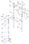
Fig. 2: The assembly
Building
Example of how a wooden rope pump can be built. Sizes in this description are guidelines and depend on local circumstances and available materials.
Sizes marked in italics are absolute, and are important for good operation or operation convenience.
Required tools
- wood saw
- metal saw
- rasp
- file
- knife/breadslicer
- punch
- little drill
- sand paper
- hammer
- scissors
Required materials
- (PVC) tube (2 sizes)
- connectors
- (PVC) glue
- inner tube (bike)
- car-tyre
- pieces tinplate
- wooden beams + boards
- stone
- rope
- nails
- bottle
- carbolineum
The frame
Figure 2 shows how the separate parts must be put together to make a rope pump.
First the posts (a), which hold the spindle (b), have to be made. The length of the posts is equal to the average elbow height (Height from ground (feet) to elbow) of the people who operate the pump plus the length which will be buried in the ground. In Europe a elbow height of 105 cm is a good average. The posts have to be buried at least 1 metre in the ground. The post length in our example must be at least 205 cm and is made of a beam of 5*10 cm.
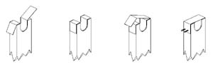
Fig. 3: Construction of the bearing
At the top of the posts a notch has to be made where the spindle will lay in. The notch has to be circular at the bottom, and just as deep and wide as the beam of which the spindle is made. Now the posts have to be protected against influence of weather. This is best done with carbolineum. When the posts are dry after treatment with carbolineum the posts can be buried at both sides of the well, in such a way that they stand firmly.
A strip of tinplate (j1) can be folded in the notches as indicated in fig.3a&b. The strips may not stick outside the wood, and must be sufficiently long so they can be attached to the outside of the posts.
The spindle
The length of the spindle (b), made of a beam of 5*5 cm, can be adjusted so that on both sides of the posts the spindle sticks out approximately 15 cm. The spindle has to be round off with the rasp where the notches in the posts touch the spindle so it can turn without too much space for motion in the notches. The length of the round off has to be a little (5 mm) wider than the thickness of the posts so the spindle can turn freely.
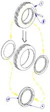
Fig. 4: Preparation of the carr-tyre
The wheel
To finish the spindle the car-tyre has to be prepared. The car-tyre (t) has to be cut off (fig 4) on both sides at about 5 à 6 cm from the inside (where the tyre laid in the wheel rim). The easiest way to do this is with a knife/breadslicer. Make sure the knife and tyre are wet so that the knife cuts easier through the tyre. The two cut-out tyre pieces must be lain against each other in a V-form. Where the pieces touch each other they must be attached to each other with 8 nails. Hit the 8 nails at about 8 mm of the inner edge through the tyre pieces.
Now a nice circular wheel with a good V-form is made. The V-form has to be sufficiently open so the rope with the pistons can lay in the V nicely.
Notes figure 4:
#: cut the tyre all the way around here
*: nail the tyre-parts together here
The spindle (continuation)
In our example we used a tyre with an inner diameter of 360 mm (where the tyre laid in the wheel rim).
The wheel is jammed around spokes. The spokes have to be a bit bigger than the inner diameter of the tyre. The spokes are made of 2 boards (c) of 10*370 mm with a thickness of 18 mm. These boards are nailed to the spindle (b) where the raising tube (m) comes out. Now lay the wheel (t-a) around the boards (c) and on each side shove a block (d) between the boards and the wheel so that they're firmly attached. In our example we used 2 blocks of 50*50 mm and a length of 145 mm. The total diameter on the place of the blocks: (blocks) 2*145 + (board thickness) 2*18 + (spindle) 50 = 376 mm. The blocks don't have to be nailed because they're firmly tightened by the tyre.
The handle
The handle (f) is made of a beam, the beam has to have the same proportions as the beam of which the spindle (a) is made (50*50). The length of the handle must be as large as the width of the boards (e) through which it is connected to the spindle plus 20 cm for the grip of the handle. In this example this is 30 cm with a board breadth of 10 cm. The length for the grip has to be rounded so a synthetic tube (g) (round 40 mm, length 20 cm) can easily turn around it. The grip with which the spindle is turned has to be attached at a distance of 20 cm from the spindle, as shown in figure 2. For this we use 2 boards (e) of 10*25 cm with a thickness of 18 mm. The spindle and grip can be attached to the boards with nails or screws.
The spindle with its roundings can now be put in the notches of the posts.
The raising tube
The length of the raising tube (m) depends on the depth of the well (front figure). The raising tube should not touch the bottom of the well, but has to hang at least 15 cm (or 6") above the bottom. A widening (o) with a length of at least 30 cm has to come at the top of the raising tube which hangs underneath the wheel (t-a) but doesn't touch the wheel.
With this data we can calculate the length of the raising tube (m). This is the length from the bottom of the well to the wheel, minus about 45 cm (30+15). This is the pump height. According to table 1 or 2 (dependent on the tyre-size used for the wheel) the tube diameter can be determined. The tube with the desired length is probably not sold in one piece but as can be seen in figure 2, several lengths of tube can be glued together using fitting sockets (n). At the bottom a funnel-shape (m-t) must be made. This can be done by gently warming the tube so that it becomes elastic and moulded into the desired shape with the use of a small bottle or something similar. Make sure the funnel-shape is without dents on the inside, which would prevent the pistons (v) to enter smoothly.
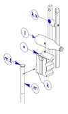
Fig. 5: Composition of the inlet block
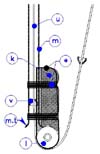
Fig. 6: Position between the different parts of the inlet block
The inlet block
For the inlet block is needed: a small bottle (l) of 33 cl or even better the famous coca cola bottle, and a piece of wood (k) approximately as thick as the bottle (l) and with a height and length of 10*20 cm. Figure 5 (seen from the underside) shows how these items are connected together and figure 6 shows the positions in more detail. (The star refers to the rubber strips wich are used to tight everyhting together.)
The bottle needs to be made heavier with wet sand and closed off with a cork. Over the length of the piece of wood a groove is made in which the raising tube (m) falls (about ¼ part of the tube diameter). At the lower side another groove has to be made so the bottle falls in it nicely. Here too, the bottle falls in it for about ¼ part. If the bottle and the end of the raising tube (with the funnel (m.t) against the bottle) are placed in the piece of wood, then it shows that the tube doesn't lay perfectly in the groove at the place of the funnel. Remove at the place of the funnel some extra material such that the tube with the funnel falls perfectly in the groove and lays well against the bottle. This place is marked with a star (*) in figure 5.
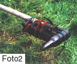
Photo 2: The inlet block
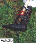
Photo 3: The inlet block
The upper side of the piece of wood must be rounded off so that the pistons don't get caught behind it. The bottle and the outlet tube can be tied to the piece of wood with 2 cm wide strips of inner tube (bicycle or car). Beforehand some notches must be made in the piece of wood where the inner tube can lay in. Again, this is done to prevent the scouring of the rope against the strips of inner tube.
To make sure the rope actually glides over the bottle and doesn't slip of, two leading-laths (k.x) with in between a piece of PVC-tube must be attached to the inlet block where the rope glides across. Only in figure 5 is shown how this looks like. At the ends of the laths grooves can be made. Here a stone can be tightened to it using a rope to heavy the inlet block, so that the raising tube hangs in the well straight. Make sure that the laths are smooth and well rounded in order to avoid that the rope with the pistons get caught.
The widening and outlet
As said before the top of the tube must be a bit wider than the raising tube itself. This can be done in several ways. The easiest manner is shown in figure 2, namely with a piece of tube (o) with a larger diameter, which is glued to the raising tube (m) using a reducing ring (p). Close to this glue-point a T-piece (q) must be glued in the wider tube on the place where the outlet tube (r.) can be glued on. Please look after that the inlet block is in the right position, when you glue the T-piece on the raising tube. Figure 8 shows which mistakes have to be avoided. The length of the outlet tube must be such that the water comes out of the well and a bucket must be able to be put under it. At the end of the outlet tube a bend (s) is glued to point the water stream downward instead of far away.
The widening can also be made of for example a small plastic barrel or bottle.

Fig. 7: The pistons
The pistons and the rope
Before the ropepump can be completed, the rope (u) with the pistons (v) must be made first. See figure 7. The pistons can be punched from a piece of leather or rubber with a punch. The leftovers from the piece of tyre (t-b) are well suited for this. Use the remaining side because the tread consists of steel wire, which can't be punched through. A punch can be made from a piece of steel pipe with an inner diameter the same size as raising tube. By filing one side sharp the pistons can be easily punched out of the material. If the pistons aren't the right size yet, the punch must be filed till the pistons have the right size. The right size of the pistons is when they have a tolerance of about 0.2 to 0.5 mm in the raising tube. The pistons shouldn't jam the tube in any case. Especially with pistons with a larger diameter the strength of the material used is very important. In the middle of the pistons a hole is made with such a diameter that the rope fits exactly. This hole can be made with a little drill with the right diameter.
If more pumps are being built in the region it might be an idea to produce a more sophisticated type of pistons as shown in figure 7a. The WOT has built a prototype of a simple machine for this. Please contact the WOT if you are interested in this type of pistons. A stringed rope with a diameter of approximately 4 à 5 mm can best be used. The sort isn't so important as long as it is slightly rough. Nylon is a good and cheap sort of rope. The pistons must be placed 1 à 1.5 meter from each other on the rope. Put a knot on both sides of the piston to fix it at its place. This fixation prevents that the piston can move over the rope, which causes extra wearing. The length of the rope is about twice the length from bottom to the wheel plus 1.5 metre. Add approximately 7 cm for every knot in the rope.
When the rope has been prepared as described it can be pulled through the raising tube. The easiest way to do this is to pull a thin piece of rope with some weight underneath through the tube. The rope with pistons can be tightened to the thin rope and pulled through. Knot the 2 ends provisionally at the top. Don't forget to make a large noose where the wheel is supposed to come later.
The raising tube support
The raising tube is suspended on top of the frame so that the lower side hangs freely inside the well. The place where the raising tube is suspended depends on the final construction. The raising tube can for example be suspended on a beam which is fastened to the edge of the well or to the posts (a) as shown in drawings 0 & 2. In case the latter option is used, spacing blocks (i) to keep the distance are needed between the posts and the cross-beam (h). It is very important that the beam is positioned in such a way that the rope, when fitted over the wheel, leaves the raising tube (which is tied up to the beam) straight up. The rope should not be allowed to scour the edge of the tube (o).
Fig. 8: Good and wrong assembly
The assembling
Now you can lower the completely assembled tube into the well. Put the rope over the wheel (t-a), and put the spindle back on the posts. The raising tube can be fastened to the beam with strips of bicycle tire. This must be done in such a manner that the space between the top of the tube and the wheel is at least 5 cm and that the rope comes straight out of the tube. The front figure shows how everything looks like at the end. Figure 8 shows the mistakes that need to be prevented. Figure 8a shows how the different parts are well aligned, and figure 8b shows two mistakes: First the rope doesn't come out of the tube straight, and second the bottle (and also the inlet block) doesn't lay in the same angle as the wheel.
The bearing
Above the posts (a) where the spindle (b) is put in, pieces of tinplate (j2) must be folded with the same width as the underlying pieces (j1) and with such a length that they come out on the side at the same height. The pieces must now be attached to both sides of the posts with screws or nails. Figure 3 shows what is meant. Beware that the screws or nails are not too long because they would otherwise puncture the bearings and the spindle. The bearings must be greased or lubricated regularly.
The finishing touch
Knitting the rope
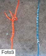
Now the two ends of the rope can be connected to form a continuous piece of rope. The place where the two ends are fastened must be thin, so it fits in small tubes easily. If a stringed rope with for example 3 strings is used, the ends can be connected as follows. Where the two ends overlap pull the rope slightly tight. The rest of the rope can be cut in such a way that the two ends still have about 20 cm overlap. Each end is loosened about 10 cm. Now the separate ends can be woven together by weaving the separated strings with the strings that weren't separated. Make sure the rope doesn't become too tight or too loose.
Another possibility is to connect the two ends with the help of a string. Shorten the rope as shown above and here it is needed as well that the two pieces have an overlap of at least 20 cm. With needle and thread the two ends can be knitted together.